Content last revised on October 17, 2026
DDB6U145N16L Thermal-Electrical Optimization: Phase-Controlled Rectification, Firing Angle Practical Tuning
- Isolate the power assembly, discharge stored energy, and compare cold terminal measurements with the equipment schematic before removing the DDB6U145N16L.
- Check terminal identification, conductor routing, and mounting alignment against the original assembly drawing.
- Inspect the heatsink contact surface, thermal interface coverage, and accessible insulation surfaces for contamination or mechanical damage.
- Record the fuse designation and protective circuit connections before disconnecting the rectifier assembly.
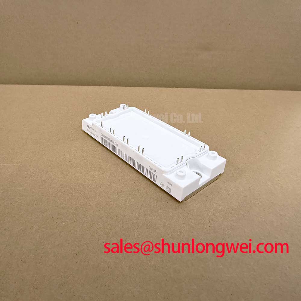
The Infineon DDB6U145N16L is a diode module with the electrical ratings below. Its integration assessment should distinguish rectification duties from the controlled switching functions performed elsewhere in the equipment.
| Parameter | Official Specification |
|---|---|
| Repetitive peak reverse voltage, VRRM | 1600 V |
| Average forward current, IFAV | 145 A at TC = 80 °C |
| Forward voltage, VF | 1.25 V typical at 25 °C, IF = 150 A |
| Maximum junction temperature, Tvj max | 150 °C |
| Terminal map, mounting torque, surge withstand, I²t, and recovery characteristics | Consult Datasheet |
Trace the power circuit to identify which devices actually receive firing commands before adjusting any rectifier control settings. The DDB6U145N16L is a diode module; firing angle control belongs to thyristors or another controlled stage in the surrounding circuit. Assigning a firing angle to this module would confuse its conduction behavior with the controller’s operation.
Design Consideration: when a surrounding controlled converter delays conduction, its average output, input current waveform, displacement power factor, and reactive power demand can change. The relationship depends on bridge configuration, load continuity, and commutation overlap. Commissioning should therefore compare commanded firing timing with measured line current and output voltage, rather than applying a controlled bridge transfer characteristic to the diode module itself.
The 145 A at TC = 80 °C rating makes case temperature a defined operating condition. The 1.25 V typical forward drop describes the stated test point; it does not establish hot operating losses across an entire load waveform. Engineering Recommendation: evaluate conduction heating using the applicable forward characteristic and actual current waveform, then assess the thermal path against the 150 °C junction limit.
Design Consideration: thermal interface material should fill surface irregularities without preventing proper seating. Select application thickness, fastening sequence, and mounting torque from the mechanical instructions. When evaluating the module within a high-voltage three-phase motor solid-state soft starter, establish its rectifier or auxiliary supply role separately from the motor’s phase control devices.
DDB6U145N16L Operational Boundaries: Evaluating High-Frequency Switching Loss Dissipation Limits
Capture diode current and reverse voltage during the actual commutation event before assessing recovery losses. The stated voltage, current, and forward drop specifications do not establish a fast recovery classification, reverse recovery peak current, recovery time, or softness factor.
Design Consideration: reverse recovery depends on the preceding forward current, junction temperature, applied reverse voltage, and current commutation rate. Recovery softness describes the shape of the recovery current decay; it cannot be inferred from the forward voltage. Where commutation produces ringing, compare current and voltage traces with the circuit’s switching sequence and probe arrangement before attributing the disturbance to the module.
Design Consideration: minimize unnecessary loop area and keep outgoing and return power paths close to reduce inductive voltage excursions. Evaluate any MOV or snubber network against repetitive voltage stress, transient energy, and interaction with circuit inductance. Its selection belongs to the complete power assembly and requires measured transient validation.
Practical tip: preserve compact, balanced power connections during replacement and verify commutation overshoot under controlled load before returning the assembly to service.
Gate drive, Miller coupling, and Kelvin emitter routing concern adjacent controlled switches, rather than terminals to assign to this diode module. The Unlocking Efficiency in Industrial Drives article provides related inverter context, while Infineon OptiMOS™ & CoolMOS™ Power MOSFETs addresses a separate controlled device family.
Field Diagnostics & Commissioning: Short-Circuit Withstand Limits: Coordination in DDB6U145N16L Topologies
Match the fuse’s total clearing I²t to the semiconductor’s applicable withstand conditions before approving protection coordination. Engineering Recommendation: compare matching pulse conditions, initial temperature, prospective fault current, and applied voltage; interrupting capacity and peak let-through current also require assessment. An I²t comparison alone cannot guarantee damage-free interruption.
| Coordination item | Engineering assessment |
|---|---|
| Semiconductor withstand | Use the applicable surge current and I²t limits with their temperature and pulse conditions. |
| Fuse clearing behavior | Assess total clearing I²t and peak let-through at the prospective fault current. |
| Fault interruption | Check fuse voltage rating, interrupting capacity, and protective circuit operation. |
Design Consideration: maintain terminal creepage and clearance according to the equipment’s insulation requirements, pollution conditions, and installation environment. Inspect conductor positioning after tightening; mechanical fit alone does not establish electrical compatibility.
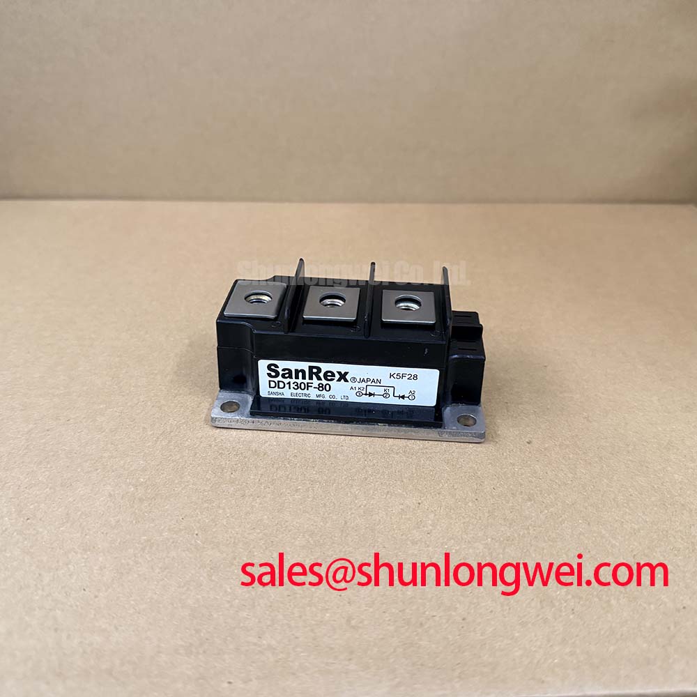
For replacement assessment, compare DDB6U215N16L against the complete terminal arrangement, thermal requirements, and protection limits before treating it as interchangeable. Where the schematic includes a separate rectifier or auxiliary branch, assess DD180N16S within that branch’s requirements. Complete commissioning by checking connection heating, case temperature, and protection operation under the equipment’s approved test procedure.