
Content last revised on September 29, 2026
What This Component Is and Its Industry Significance
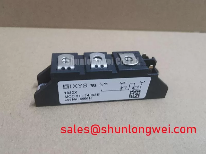
The IXYS MCC21-14IO8B is an industrial-grade, isolated-base power module engineered for robust electrical conversion and control in medium-voltage, medium-power systems. Packaged in a compact, industry-standard dual-semiconductor housing, the device provides an official repetitive peak off-state and reverse voltage rating of 1400 V and an average on-state forward current rating of 21 A. While traditionally classified under phase-control dual thyristor topologies, devices within this package family serve as essential building blocks across modern power conversion architectures, operating in close coordination with advanced Insulated-Gate Bipolar Transistor (IGBT) Fundamentals to deliver stable, efficient power delivery.
In modern industrial systems, power electronics must reliably handle severe thermal cycling, substantial electrical overloads, and high transient line voltages without unexpected failure. Discrete through-hole or surface-mount packages often struggle to meet these demands due to inadequate internal creepage distances, limited surge current ratings, and the high thermal resistance inherent in non-isolated packages. The MCC21-14IO8B addresses these challenges by incorporating an electrically isolated Direct Bonded Copper (DBC) baseplate. This architecture allows multiple power modules to be mounted directly onto a shared chassis or heatsink without requiring fragile external mica or silicone insulating pads, significantly simplifying assembly and lowering system parasitic inductance.
The significance of 1400 V class power modules is particularly evident in three-phase line-connected equipment running from 380 VAC, 400 VAC, and 480 VAC utility mains. In these networks, line disturbances, lightning-induced surges, and inductive load disconnects regularly produce peak transient voltages exceeding 1000 V. A 1200 V or 1400 V blocking margin ensures a solid safety boundary, preventing avalanche breakdown and catastrophic device failure. Whether functioning as the controlled input rectifier stage for an adjustable speed motor drive, managing inrush current limitation in an uninterruptible power supply (UPS), or controlling DC rail charging in a green hydrogen electrolyzer system, the MCC21-14IO8B provides the rugged front-end control needed to protect sensitive downstream high-speed switching silicon.
As industrial automation, clean energy generation, and electrified processing demand greater reliability, engineers rely on standardized, field-proven power modules. The IXYS MCC21-14IO8B represents a balance between high voltage withstand capability, manageable thermal resistance, and compact mechanical integration, ensuring uninterrupted service in demanding commercial and heavy-duty electrical installations.
Working Principle and Physical Structure
To understand how power modules like the MCC21-14IO8B and related IGBT power assemblies control electrical currents, one must evaluate both their microscopic semiconductor behavior and their internal mechanical construction. At the device physics level, power semiconductors regulate the transit of mobile charge carriers (electrons and holes) through carefully structured, alternating regions of p-type and n-type silicon.
In voltage-driven switching devices like the IGBT, conduction is governed by an insulated metal-oxide-semiconductor (MOS) gate structure positioned above a wide, lightly doped n-type drift layer and a heavily doped p-type collector substrate. When the gate-to-emitter voltage (VGE) is zero or negative, the junction remains reverse-biased, supporting hundreds or thousands of volts across the drift region while drawing only negligible leakage current. Once VGE exceeds the internal threshold voltage (VGE(th)), an electrostatic field creates an inversion channel across the p-base. Electrons enter this channel from the emitter, causing the p-collector junction to inject minority carrier holes into the lightly doped drift layer. This flood of carriers dramatically lowers the bulk resistance of the drift region—a physical mechanism known as conductivity modulation. Because of conductivity modulation, the forward on-state saturation voltage drop (VCE(sat)) remains remarkably low, even at high operating currents.
In phase-controlled thyristor switches like those in the MCC21 series, a four-layer p-n-p-n structure is governed by current injection into a gate electrode. When a brief current pulse is delivered across the gate-cathode terminals under forward voltage, internal regenerative feedback drives the four-layer structure into deep saturation. The device latches in the conducting state, sustaining low forward conduction loss until the external anode current naturally drops below the critical holding current (IH). Both topologies rely on high carrier density in the active silicon volume during on-state conduction, offset by the need to sweep out or recombine stored charge carriers when turning off.
Figure 1: Internal cross-section showing baseplate, DBC ceramic, semiconductor die, and terminal assembly
Mechanically, the internal build of the MCC21-14IO8B is designed to manage intense thermal flux and severe mechanical stress. The semiconductor dies are soldered directly to a DBC substrate, which consists of a high-purity aluminum oxide (Al2O3) or aluminum nitride (AlN) ceramic core bonded between two heavy copper foil layers. The upper copper layer is chemically etched to form the internal circuit tracks and die attachment pads, while the lower planar copper sheet is soldered to a nickel-plated copper baseplate.
Electrical interconnections between the top surfaces of the silicon dies and the package terminals are made using multiple ultrasonic aluminum wire bonds. The complete internal cavity is then filled with a soft, dielectric silicone gel and sealed within a flame-retardant thermoplastic housing (UL 94 V-0 compliant). The silicone gel cushions the silicon dies and wire bonds against mechanical shock and thermal expansion mismatches, while preventing moisture ingress and high-voltage surface arcing. This multi-layer mechanical sandwich ensures reliable thermal dissipation from the silicon junction (Tj) down through the baseplate to the external heatsink.
Key Features, Advantages, and Technology Comparison
The IXYS MCC21-14IO8B stands out in industrial power conversion systems due to its specific electrical ratings, proven mechanical reliability, and predictable operational behavior. Evaluating these characteristics reveals how the module maintains high efficiency and circuit stability under demanding operating conditions.
Primary technical characteristics of the module include:
- 1400 V Repetitive Peak Voltage (VRRM / VDRM): Guarantees a substantial voltage blocking margin when connected to 400 VAC and 480 VAC industrial distribution systems subject to switching noise and line surges.
- 21 A Continuous Current Rating: Provides stable current carrying capacity across industrial control cabinets, heating controllers, and auxiliary motor drive circuits.
- Electrically Isolated Baseplate: Incorporates advanced DBC ceramic technology rated for electrical isolation up to 2500 V to 3000 V RMS, enabling multi-module heatsink sharing and reducing assembly time.
- High Surge Current Capability (ITSM): Absorbs short-duration fault currents and capacitive inrush spikes without junction degradation, protecting downstream circuitry.
- Planar Passivated Silicon Dies: Delivers long-term parameter stability, low off-state leakage currents (ID, IR), and resilient performance at junction temperatures up to 125 °C or 150 °C.
- Standardized Mechanical Footprint: Uses robust screw terminals and dual mounting holes to ensure stable mechanical clamping and low electrical contact resistance.
To assist system engineers in selecting the right power semiconductor topology for their application, the table below compares the MCC21-14IO8B with alternative modern power modules, such as the trench Field-Stop IGBT DP15H1200TO101982, the heavy-duty planar IGBT module QM300HA-H, and the fast-recovery bridge module SKD75GAL123D.
| Device / Module Part Number | Semiconductor Technology | Voltage Rating (VCES / VRRM) | Nominal Current (IC / IT(AV)) | Typical Conduction Drop | Switching Frequency Capability | Primary Functional Role |
|---|---|---|---|---|---|---|
| IXYS MCC21-14IO8B | Dual Phase-Control Thyristor | 1400 V | 21 A | VT ≈ 1.35 V | Line frequency (50/60 Hz to 400 Hz) | Controlled rectification, soft-start, DC pre-charge |
| DP15H1200TO101982 | Trench Field-Stop IGBT | 1200 V | 15 A | VCE(sat) ≈ 1.90 V | High (up to 20 kHz) | Precision motor drives, compact inverters |
| QM300HA-H | High-Power Planar IGBT | 600 V / 1200 V Class | 300 A | VCE(sat) ≈ 2.20 V | Medium (up to 10 kHz) | Heavy-duty traction, industrial propulsion |
| SKD75GAL123D | Bridge Rectifier + Chopper | 1200 V | 75 A | VF ≈ 1.25 V / VCE ≈ 2.0 V | Line rect. / 15 kHz chopper | Braking choppers, regenerative drive front-ends |
As the comparison shows, the MCC21-14IO8B is optimized for low-frequency line rectification and high-surge line-frequency control. While fast-switching IGBT modules handle high-frequency pulse-width modulation (PWM) in the inverter stage, the MCC21-14IO8B provides a low on-state voltage drop and superior surge handling at the power entry point. This makes it an effective companion module in comprehensive conversion systems.
Real-World Applications and Operating Precautions
The MCC21-14IO8B is widely used in systems requiring reliable AC-to-DC conversion, phase control, and electrical inrush management. When integrated into modern industrial cabinets, it operates in tandem with broader Power Electronics Principles to maintain stable power distribution across critical processes.
Key Application Topologies
- Green Hydrogen Electrolyzer Rectifiers: High-current DC electrolyzers require tightly regulated DC power supplies. Controlled thyristor modules work alongside downstream filtering and multi-phase step-down conversion stages to modulate current density and handle varying load conditions during hydrogen generation.
- Variable Frequency Drive (VFD) Pre-Charge Circuits: Large DC bus capacitor banks in motor drives draw massive charging currents at initial power-up. Placing the MCC21-14IO8B in the input rectification stage enables controlled phase-angle ramp-up, eliminating the need for bulky mechanical contactors and power pre-charge resistors.
- Solid-State Motor Soft-Starters: By gradually increasing the AC conduction angle during induction motor startup, the module limits mechanical shock on gearboxes and prevents severe line-voltage dips on the plant grid.
- Industrial Process Heating and Smelting: Precise phase-angle power control delivers fine temperature regulation in induction furnaces, resistance ovens, and chemical heating vessels.
Figure 2: Heatsink mounting, thermal compound layer, and snubber protection layout
Crucial Operating Precautions
To achieve high reliability and prevent premature field failures, installation and operations teams must observe several engineering precautions:
1. Thermal Interface and Heatsink Mounting: Proper heat transfer away from the module baseplate is essential. The mounting surface of the heatsink must be machined flat to within 20 µm per 100 mm, with a surface roughness (Ra) not exceeding 1.6 µm. A thin, uniform layer of high-performance thermal grease (thermal conductivity ≥ 1.5 W/m·K) must be applied across the baseplate at a thickness of 50 µm to 100 µm. Excessive thermal paste creates thermal resistance, while insufficient paste leaves micro-voids containing trapped air. Mounting bolts (typically M4 or M5) should be torqued in a balanced, two-stage sequence up to the recommended tightening torque of 1.5 to 2.5 N·m to ensure even baseplate seating without mechanical warping.
2. Transient Voltage and Snubber Suppression: Stray inductance in power busbars and long cable runs can generate destructive transient voltage spikes (V = -L × dI/dt) during rapid reverse recovery and commutation. RC snubber networks (typically 0.1 µF to 0.47 µF polypropylene capacitors paired with low-inductance 10 Ω to 47 Ω resistors) or metal-oxide varistors (MOVs) should be placed as close to the AC and DC terminals as possible to clamp overvoltage spikes well below the 1400 V maximum limit.
3. Gate Drive and Trigger Isolation: Gate control lines must use twisted pairs or shielded wiring routed well away from high-current power terminals to prevent capacitive coupling and electromagnetic interference (EMI). Unintentional gate noise can cause false triggering, potentially shorting the AC mains. Pulse transformers or optical isolators should provide galvanic isolation between the low-voltage control processor and high-voltage power paths.
4. Electrostatic Discharge (ESD) Measures: While thyristor gates are mechanically tougher than sub-micron MOS gates, high static charges can still cause microscopic pinhole defects in silicon passivation layers. Technicians should always handle modules using grounded wrist straps, static-dissipative workstations, and conductive packaging materials.
Engineering Selection Guidelines and Field Diagnostics
Selecting the right power semiconductor module requires balanced engineering calculations. An incorrectly sized module may result in unexpected thermal shutdown, shortened service life, or catastrophic electrical breakdown under routine line disturbances.
Voltage and Current Derating Methodology
In power semiconductor design, components must never be operated at their absolute maximum datasheet ratings. For a 400 VAC nominal three-phase supply, the peak phase-to-phase line voltage is approximately 400 × √2 ≈ 565 V. However, utility networks regularly experience transients caused by transformer switching, power factor correction capacitor banks, and nearby lightning strikes. To ensure a dependable safety buffer, engineers apply a voltage derating factor (kv) of 2.0 to 2.5:
VRRM(required) ≥ Vline(RMS) × √2 × kv
For a 400 VAC system, 565 V × 2.2 = 1243 V. The 1400 V rating of the MCC21-14IO8B fits this requirement comfortably, ensuring stable long-term operation. For continuous current sizing, the device current rating must be derated based on maximum enclosure temperature and heatsink efficiency. If the total calculated continuous average current in the converter leg is 14 A, operating the 21 A rated MCC21 module ensures the average steady-state junction temperature remains comfortably below the 125 °C maximum limit, using the classic thermal resistance formula: Tj = Tambient + Ploss × (Rth(j-c) + Rth(c-s) + Rth(s-a)).
Field Diagnostics and Troubleshooting
When commissioning a new power assembly or troubleshooting an operational system that has tripped an overcurrent or ground fault alert, a digital multimeter (DMM) can quickly determine the functional status of the module. Ensure all AC main power and DC bus supplies are completely disconnected, discharged, and verified with a calibrated voltmeter before touching power terminals.
| Test Step | Multimeter Mode | Meter Lead Connections | Normal Expected Reading | Abnormal / Fault Reading | Suspected Failure Root Cause |
|---|---|---|---|---|---|
| 1. Forward Blocking Test | Diode Test / Resistance | Positive to Anode, Negative to Cathode | Open Loop ("OL") / > 1 MΩ | 0.00 V to 0.05 V (Short circuit) | Thermal runaway, overvoltage punch-through, or baseplate melt. |
| 2. Reverse Blocking Test | Diode Test / Resistance | Positive to Cathode, Negative to Anode | Open Loop ("OL") / > 1 MΩ | Low resistance (< 50 Ω) or "Short" | Reverse voltage surge beyond 1400 V or degraded passivation layer. |
| 3. Gate-Cathode Junction | Resistance (Ω) | Between Gate (G) and Cathode (K) leads | Typically 10 Ω to 200 Ω (both directions) | Open Loop (> 100 kΩ) or Near 0.00 Ω | Gate wire bond lifted (open circuit) or severe gate driver surge. |
| 4. Dielectric Isolation Test | Insulation Tester (500 VDC) | Any Power Terminal to Metal Baseplate | > 100 MΩ (infinite isolation) | < 5 MΩ or direct continuity | Cracked internal ceramic DBC substrate due to overtorquing or thermal shock. |
If the module passes these static bench tests, dynamic gate pulsing and load commutating tests can be performed at rated operating voltage. Always verify that gate pulse width, peak gate current (IGM), and rate of current rise (dI/dt) match manufacturer application notes to prevent localized silicon hot spots. By combining thorough visual inspections, correct thermal mounting, and standardized diagnostic routines, commissioning engineers can ensure safe, long-term operation across modern industrial power conversion systems.