Content last revised on October 21, 2026
FF1000R17IE4D_B2 Thermal-Electrical Optimization: Screening for DBC Substrate Ceramic Micro-Cracks
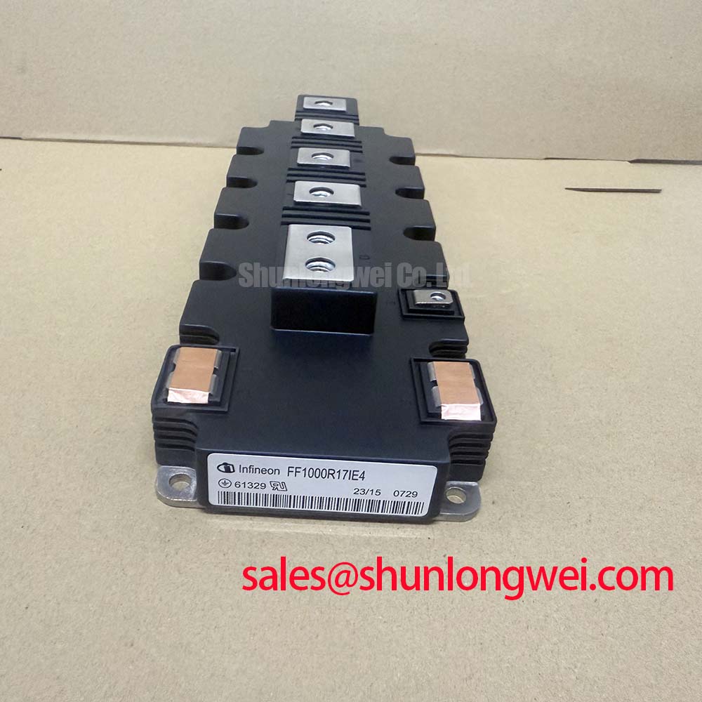
With the DC link discharged and the module disconnected from its driver, match each power and control terminal to the manufacturer’s terminal diagram before taking cold-state measurements. Record meter polarity, instrument mode, and module temperature so that a later comparison uses the same conditions. The Infineon FF1000R17IE4D_B2 is an IGBT module with a 1700 V voltage rating and a 1000 A collector-current rating under the datasheet’s specified conditions. These ratings identify the device’s electrical class; incoming inspection must also establish terminal consistency and suitability for the intended assembly.
💡 Bench Tip: Use ESD protection and compare cold-state readings with a documented reference module under identical meter conditions, keeping the gate from floating during handling.
Separate terminal-to-baseplate insulation assessment from semiconductor junction testing: the instruments, electrical stresses, and interpretation are different. As a Design Consideration, an insulation test should follow an approved procedure that defines terminal grouping, test voltage, duration, environmental conditions, and post-test discharge. Disconnect the gate driver, sensors, and other attached electronics before applying any insulation-test voltage.
The 1700 V device rating must not be treated as the terminal-to-baseplate insulation-test specification. Establish the applicable insulation requirements from the manufacturer’s documentation and the equipment service procedure. For manufacturer context, the Infineon IGBT Modules Overview provides access to its module portfolio; the exact part documentation remains the reference for device-specific limits.
Inspect exposed insulating surfaces, terminal recesses, and the mounting interface before interpreting an abnormal reading. Dust, moisture, handling residue, and conductive contamination can introduce surface leakage without establishing an internal substrate defect. Record the condition before cleaning, use an approved cleaning method, and repeat the measurement under controlled conditions. A changed reading can help distinguish surface contamination from a persistent insulation concern, but it does not identify the internal failure location.
Keep external wiring, mounting hardware, and grounded metalwork outside the clearance envelope established for the equipment. Creepage suitability depends on the assembly’s working voltage, insulation coordination, and environmental conditions rather than the module’s current rating. If persistent leakage or visible mechanical damage remains, segregate the unit for further evaluation; neither an insulation-resistance reading nor a visual inspection alone certifies the absence of internal ceramic cracking.
FF1000R17IE4D_B2 Operational Boundaries: Evaluating Antiparallel Freewheeling Diode Reverse Recovery Limits
Use the multimeter’s diode mode to compare the expected freewheeling conduction paths only after confirming terminal polarity and controlling the gate state. Record forward-direction and reverse-direction indications with the same lead arrangement for each equivalent path. Connected busbars, discharge networks, and driver circuitry can influence the result, so isolate those paths before attributing an unexpected reading to the module.
As a Design Consideration, this cold-state check screens gross electrical inconsistencies; it does not measure peak reverse-recovery current, recovery charge, or recovery softness. During commutation, stored charge and the external circuit determine the recovery waveform. An abrupt recovery-current transition can excite parasitic inductance and capacitance, producing ringing that requires investigation at the switching node rather than diagnosis from a diode-mode reading.
For dynamic evaluation, capture current and voltage with suitable probes, controlled probe geometry, and a documented operating point. Compare recovery behavior at the intended current and temperature conditions. Engineers may evaluate turn-on gate resistance or a snubber to reduce excessive excitation, but the resulting switching losses, voltage peaks, and component heating need assessment together. Neither gate resistance nor snubber values should be selected from the module’s headline ratings alone.
Keep the recovery-current loop compact and consider how its routing couples into control wiring. Where gate-drive timing is reviewed, assess propagation differences and switching transitions before setting dead time; excessive dead time can also change diode conduction losses. Recovery-related ringing is one contributor to equipment emissions, not proof of compliance or noncompliance with an EMC standard.
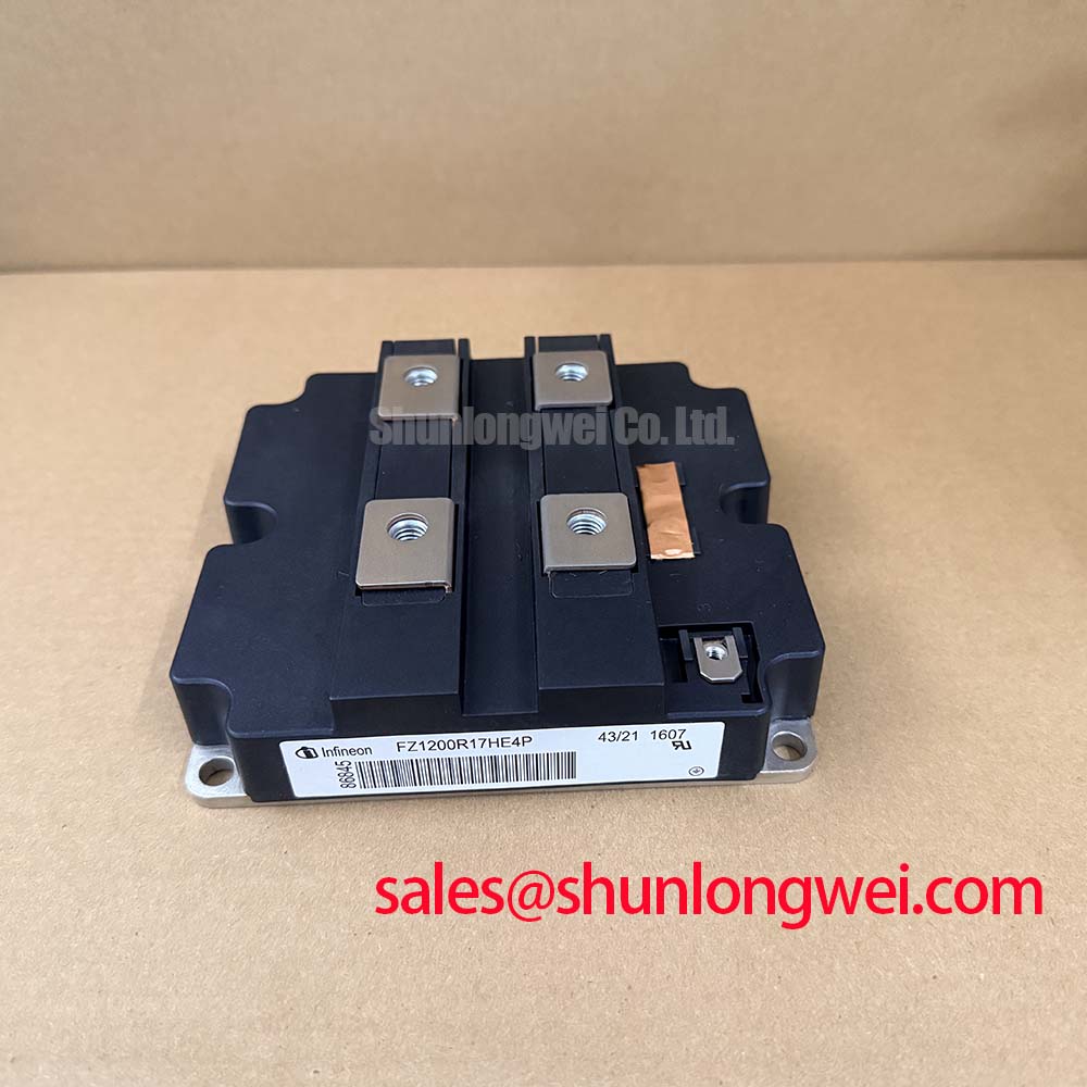
A comparison with FZ1200R17KF6-B2 should therefore begin with the electrical configuration and terminal drawing, not a presumed interchangeability based on the model family.
| Comparison item | FF1000R17IE4D_B2 | FZ1200R17KF6-B2 |
|---|---|---|
| Manufacturer | Infineon | Consult datasheet |
| Rated voltage | 1700 V | Consult datasheet |
| Rated collector current | 1000 A under the datasheet’s specified conditions | Consult datasheet |
| Package classification | Module | Consult datasheet |
| Replacement assessment | Compare circuit configuration, terminal arrangement, mechanical drawing, gate-drive requirements, diode characteristics, and thermal conditions before approving a substitution. | |
FF1000R17IE4D_B2 Circuit Protection & Reliability: Checking Heatsink Surface Flatness and Thermal Grease Application
Inspect the heatsink contact area for raised burrs, embedded particles, machining damage, and residual interface material before placing the module. As a Design Consideration, surface condition affects contact uniformity: additional grease cannot reliably compensate for a damaged mounting surface. Measure flatness using the method and acceptance criteria specified for the mounting assembly.
Evaluate the module’s mounting surface against its mechanical requirements rather than assuming that any visible curvature is defective. The mounting procedure must account for the permitted baseplate geometry and the heatsink’s condition together. Avoid sanding or mechanically reshaping the module to obtain an apparently flat contact face; such work changes the assembly conditions without establishing acceptable internal stress.
Use a calibrated torque tool and the prescribed fastener arrangement. Where the manufacturer’s assembly instructions specify staged cross-pattern tightening, follow that sequence so that seating develops progressively across the interface. Record the applied torque and sequence separately from the inspection results. A completed torque operation demonstrates process execution, not direct proof of uniform contact pressure.
For service evaluation, compare temperature measurements at consistent locations, loading conditions, and coolant or airflow conditions. A temperature imbalance can justify checking the mounting interface, but electrical loss differences and cooling-path restrictions also require attention. The Industrial Applications resource provides broader operating context; maintenance acceptance should remain tied to the equipment’s approved tests rather than an assumed service-life figure.
Assembly Integrity & Layout Architecture: Implementing Thermal Interface Material Thickness Uniformity for FF1000R17IE4D_B2
Control thermal interface material application through the approved dispensing or stencil process, with coverage matched to the mounting surface and material supplier’s instructions. As a Design Consideration, the objective is consistent contact with limited trapped air, not an arbitrarily thick layer. Material quantity, spreading behavior, surface geometry, and tightening sequence interact, so thickness acceptance belongs to the validated assembly process.
Check application consistency on an approved process sample or inspection coupon where the production method permits it. Look for incomplete coverage, displaced material, contamination, and edge accumulation. An imprint inspection can help assess spreading, but separating the surfaces disturbs the interface; clean and reapply material before final assembly rather than treating the inspected imprint as a finished joint.
Support power connections so that busbar alignment does not pull the seated module away from its intended mounting position. Check terminal engagement and mechanical fit before final tightening, and keep control connections free from strain. The Infineon IGBT Modules & Discretes Official Portfolio is a manufacturer reference for product classification; terminal loads and installation details require the applicable device instructions.
When evaluating the FF1000R17IE4D_B2 for a utility-scale centralized battery energy storage PCS, engineers should compare its ratings, terminal configuration, cooling interface, and protection coordination with the existing converter design. Retain the terminal-check record, cold-state measurements, insulation-test conditions, interface-material identification, and tightening record with the assembly. These records make subsequent thermal or electrical deviations easier to investigate without disturbing a correctly installed interface unnecessarily.