

Content last revised on May 18, 2026
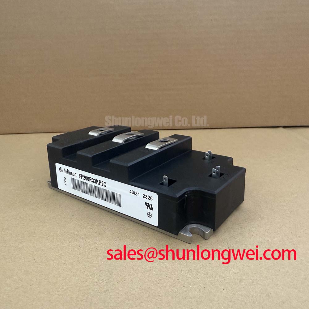
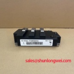
FF200R33KF2C Infineon 3300V 200A Dual IGBT Module
The Infineon FF200R33KF2C, officially designated as an IGBT-Module for inverter applications, delivers uncompromising high-voltage reliability, leveraging its 3300V capability to streamline medium-voltage drive architectures. Featuring a robust 200A continuous current rating and an exceptional 6.0 kV RMS isolation voltage, it radically simplifies system integration while ensuring absolute field longevity. For engineers scaling to 1500V+ DC links, this module eliminates the critical risk of voltage imbalance seen in series-connected lower-voltage devices. For medium-voltage traction and wind converters prioritizing insulation integrity, this 3300V module is the optimal choice.
Application Scenarios & Value
Simplifying Topologies in Medium-Voltage Converters
Engineers often face significant topological complexities when designing inverters for 1500V to 2000V DC link systems. Deploying series-connected 1700V modules introduces active voltage balancing challenges and drastically increases parasitic stray inductance. The FF200R33KF2C, with its native 3300V VCES blocking capability, resolves this structural challenge directly. What is the primary benefit of its native 3300V rating? It eliminates complex series connections in high-voltage DC links. By utilizing a single high-voltage module, designers can streamline the traction inverter or wind turbine converter architecture, improving the overall mean time between failures.
In high-power industrial drives, managing start-up surge currents and maintaining electrical isolation under severe load fluctuations is critical. The 6.0 kV RMS isolation of this dual IGBT module guarantees compliance with strict medium-voltage safety standards, such as IEC 61800-5-1, without requiring excessively complex external clearance margins. This makes it a highly rugged choice for heavy-duty operational profiles. While this 200A module is ideal for auxiliary traction or compact MV drives, for higher-capacity grid-tied inverters, the related FF400R33KF2C offers a 400A continuous rating in the same dual topology, and the FZ1200R33KF2C provides massive 1200A capacity in a single-switch configuration.
Technical Deep Dive
Decoding High-Voltage Insulation and Thermal Mechanics
Understanding the internal mechanics of the FF200R33KF2C is vital for optimizing IGBT Module deployment in multi-megawatt environments. The component relies on proven trench and planar technologies, specifically optimized to handle extreme blocking voltages while maintaining a wide Safe Operating Area.
Think of the 3300V blocking voltage and 6.0 kV RMS isolation as a reinforced high-pressure dam; it does not simply hold back a higher volume of water (the operational voltage), but it features a structurally superior containment wall (the dielectric isolation baseplate) to prevent catastrophic breaches during grid transient pressure spikes. This architectural ruggedness prevents partial discharge degradation over decades of continuous operation.
Thermally, the module operates with equal resilience. The internal Aluminum Nitride ceramic substrate acts as an engineered thermal highway. It rapidly evacuates the concentrated heat generated by the 3.4V VCE(sat) away from the silicon junctions down to the heat sink. Just as a multi-lane expressway prevents traffic bottlenecks, this low thermal resistance substrate prevents localized thermal runaway, allowing the device to endure severe power cycling in high-density power systems.
Key Parameter Overview
Critical Specifications for High-Voltage Integration
The following functional groups outline the core capabilities of the device based on official manufacturer specifications.
| Parameter Group | Specification | Value |
|---|---|---|
| Maximum Rated Values | Collector-Emitter Voltage (VCES) | 3300 V |
| Continuous DC Collector Current (IC) | 200 A (at Tc = 80°C) | |
| Repetitive Peak Collector Current (ICRM) | 400 A (tp = 1 ms) | |
| Characteristic Values | Collector-Emitter Saturation Voltage (VCE(sat)) | 3.4 V (typ, at IC=200A, Tvj=25°C) |
| Gate Threshold Voltage (VGE(th)) | 5.2 V (min) / 6.5 V (max) | |
| Insulation & Mechanical | Isolation Test Voltage (RMS, f=50Hz, t=1 min) | 6.0 kV |
| Package Configuration | IHV 73mm (Dual Configuration) |
Download the FF200R33KF2C datasheet for detailed specifications and performance curves.
Frequently Asked Questions
Engineering Insights for the FF200R33KF2C
How does the 3300V VCES rating of the FF200R33KF2C benefit medium-voltage inverter design?
It eradicates the necessity to stack 1700V modules in series for systems operating on 1500V to 2000V DC links. This directly eliminates the requirement for active voltage balancing circuitry and highly synchronized gate drives, reducing the overall component count and boosting system reliability.
What is the engineering significance of the 6.0 kV RMS isolation voltage?
This premium isolation rating provides a massive dielectric margin against grid transients, lightning surges, and high dv/dt switching spikes. It guarantees absolute insulation integrity in harsh traction environments, ensuring compliance with strict medium-voltage safety directives.
Why is a 3.4V VCE(sat) acceptable in this specific high-voltage class?
In the 3.3kV semiconductor class, the silicon die thickness required to reliably block the massive off-state voltage naturally increases the forward conduction voltage drop. The 3.4V VCE(sat) figure represents a highly optimized physical trade-off, balancing acceptable conduction losses with the rugged short-circuit capability necessary for heavy inductive loads.
Contact our engineering sales team to secure your supply of this vital high-voltage component today.