

Content last revised on October 6, 2026
FF600R12ME4_B72 Heatsink Contact and Benchtop Waveform Checks
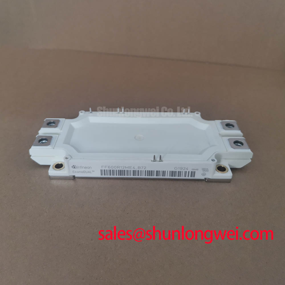
With the converter isolated and its DC link confirmed discharged, check the nameplate ratings and mounting footprint before evaluating FF600R12ME4_B72 as a replacement. The supplied official specifications identify this Infineon IGBT module with a 1200 V voltage rating and a 600 A current rating. Those figures establish screening boundaries, not confirmation that its terminals, switching behavior or cooling interface match an existing assembly. The FF600R12ME4_B72 product listing provides a reference point for the exact orderable model.
For a removed module, photograph the terminal layout, mounting positions and gate-drive connections before disturbing the assembly. Inspect the mating heatsink for raised burrs, old interface material and uneven contact marks. A surface that looks clean can still leave localized gaps under the module; conversely, excessive thermal interface material can impede rather than improve heat transfer. These are Design Considerations, not published thickness or flatness limits for FF600R12ME4_B72.
During reassembly, apply the selected thermal interface material according to its supplier’s instructions and the equipment manufacturer’s mounting procedure. Spread it consistently, avoid trapped pockets and tighten mounting fasteners progressively in the specified sequence. Do not transfer a torque value from another module or fastener size. If the original assembly shows an unusual contact pattern, check both mating surfaces and the documented mounting method before attributing elevated temperature to the semiconductor.
Thermal contact and switching waveforms need separate checks. After installation, compare case or heatsink temperature trends with the equipment’s established operating record under comparable load and cooling conditions. On a controlled bench, capture turn-on and turn-off waveforms with suitable isolated measurement equipment. A hotter assembly alongside a changed switching waveform warrants inspection of the cooling path, gate-drive connections and DC-link layout; neither observation alone identifies a failed module.
Physical fit is only the first compatibility test. Compare terminal positions, electrical clearances and the path taken by each power connection with the original design drawings. Insulation coordination is a system-level assessment: the integrator should verify creepage and clearance against the equipment’s working voltage, environment and applicable standard, rather than infer compliance from the module’s 1200 V rating.
Gate-Drive Routing and Commissioning Diagnostics
Trace the gate command and its return from the driver connector to the module before energizing the power stage. Where the documented terminal arrangement provides a separate auxiliary emitter connection, route the driver return to that connection rather than through the high-current emitter path. This Design Consideration helps limit shared-emitter impedance in the gate loop. The exact terminal assignment must be confirmed against documentation for FF600R12ME4_B72; an apparent spare terminal is not sufficient evidence.
At commissioning, observe gate-to-emitter voltage at the module connection as well as the driver output when access and probe ratings permit. A waveform that appears settled at the driver may ring at the module because of wiring inductance or return-path coupling. Compare both traces during the same switching event, then inspect connector seating, loop area and routing if they differ. Keep measurement leads short and use a probe arrangement appropriate to the common-mode voltage.
Driver source and sink capability must be assessed against the documented gate-charge and switching requirements, the selected gate resistance and the equipment’s switching conditions. No driver peak-current value or external gate-resistor value follows from the supplied voltage and current ratings alone. As an Engineering Recommendation, adjust damping only through controlled waveform tests: review turn-on behavior, turn-off ringing, switching loss and peak voltage together. Suppressing ringing at one test point does not establish adequate margin across the operating range.
If the drive board uses an optocoupler or digital isolator, evaluate its common-mode transient immunity in the installed circuit, including its supply, return and PCB layout. Unwanted gate transitions can reflect isolation-path disturbance, Miller coupling or a poor local return, so inspect the recorded gate waveform and driver fault signals before assigning a cause. In a wider converter topology, a device such as FZ800R12KS4_B2 may appear elsewhere in the power path; its electrical role and ratings must be evaluated independently rather than treated as gate-drive specifications for this module.
FF600R12ME4_B72 Protection, Derating and Replacement Fit
Record the original module’s full designation, terminal map, mounting interface and cooling arrangement before comparing candidates. The supplied 1200 V and 600 A figures are Official Specifications for FF600R12ME4_B72, but they do not establish an interchangeable switching curve, thermal impedance, insulation rating or fault response. A comparison with FZ3600R12HP4, for example, should begin with the respective manufacturer documentation and circuit requirements; similarity in product family or voltage class is not a substitution decision.
Derating is a system decision. Review the maximum DC-link condition, measured turn-off overshoot, cooling performance and current profile against the applicable datasheet limits at their stated test conditions. If modules share current in parallel, verify static and dynamic balance separately. Temperature-dependent conduction behavior may affect static sharing, while unequal busbar paths and gate-loop wiring can disturb dynamic sharing even when devices appear matched at rest. The model-specific temperature coefficient and permissible parallel arrangement require confirmation in the relevant manufacturer documentation.
For protection troubleshooting, capture the event sequence rather than relying on a single fault indication. Compare gate command, gate voltage, DC-link behavior and current feedback around the trip. Inspect the desaturation or overcurrent response specified by the existing driver design, and check whether its blanking and shutdown behavior remain appropriate after any circuit change. A repeatable trip at a particular operating point can guide further measurement, but it does not by itself distinguish a module fault from a sensor, driver or busbar issue.
A multi-megawatt offshore or onshore wind turbine full-scale converter is one possible compatibility assessment, not a stated application approval for FF600R12ME4_B72. Its maintenance team would need to reconcile the converter schematic, fault-protection strategy and mechanical assembly before approving use. For broader background on switching behavior in industrial drives, Unlocking Efficiency in Industrial Drives can inform the questions asked during testing; it should not be used to assign an unverified chip generation or performance figure to this module.
DC-Link Busbar Geometry and Turn-Off Voltage Boundaries
Inspect how the DC-link supply and return approach the module before selecting a snubber or changing the gate resistor. Closely coupled, symmetrical conductors are a Design Consideration for limiting loop inductance and differences between current paths. The turn-off peak rises with DC-link voltage and with the voltage induced by stray inductance as current changes; therefore, verify peak collector-to-emitter voltage during representative switching tests against the module’s 1200 V Official Specification and all applicable operating limits. The supplied data do not justify a universal busbar-inductance target or snubber capacitance.
Snubber selection depends on measured overshoot, ringing, energy and the physical connection to the switching loop. Place any candidate network where its actual current path can be assessed, then repeat measurements across the relevant load and DC-link conditions. A metal-oxide varistor may be considered for a separately defined surge-protection function, but it should not be assumed to replace local switching-transient control. Its coordination with other protection elements belongs to the converter design.
💡 Pro Tip: Check busbar symmetry and measure turn-off peaks before changing gate resistance, so a layout-induced overshoot is not mistaken for a driver-setting problem.
Keep technology comparisons within their documented scope. Infineon’s automotive-qualified power module information concerns a distinct qualification context, while its power MOSFET portfolio covers a different device category. Neither source establishes automotive qualification or MOSFET characteristics for FF600R12ME4_B72. For this module, close the integration check with the exact manufacturer datasheet, the converter’s insulation and protection requirements, and waveforms measured on the installed power stage.