

Content last revised on September 10, 2026
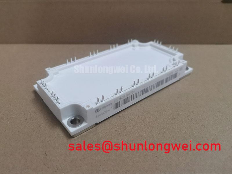
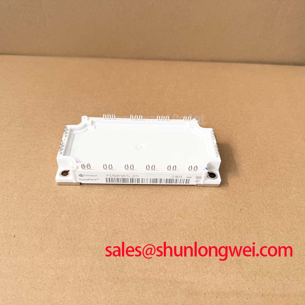
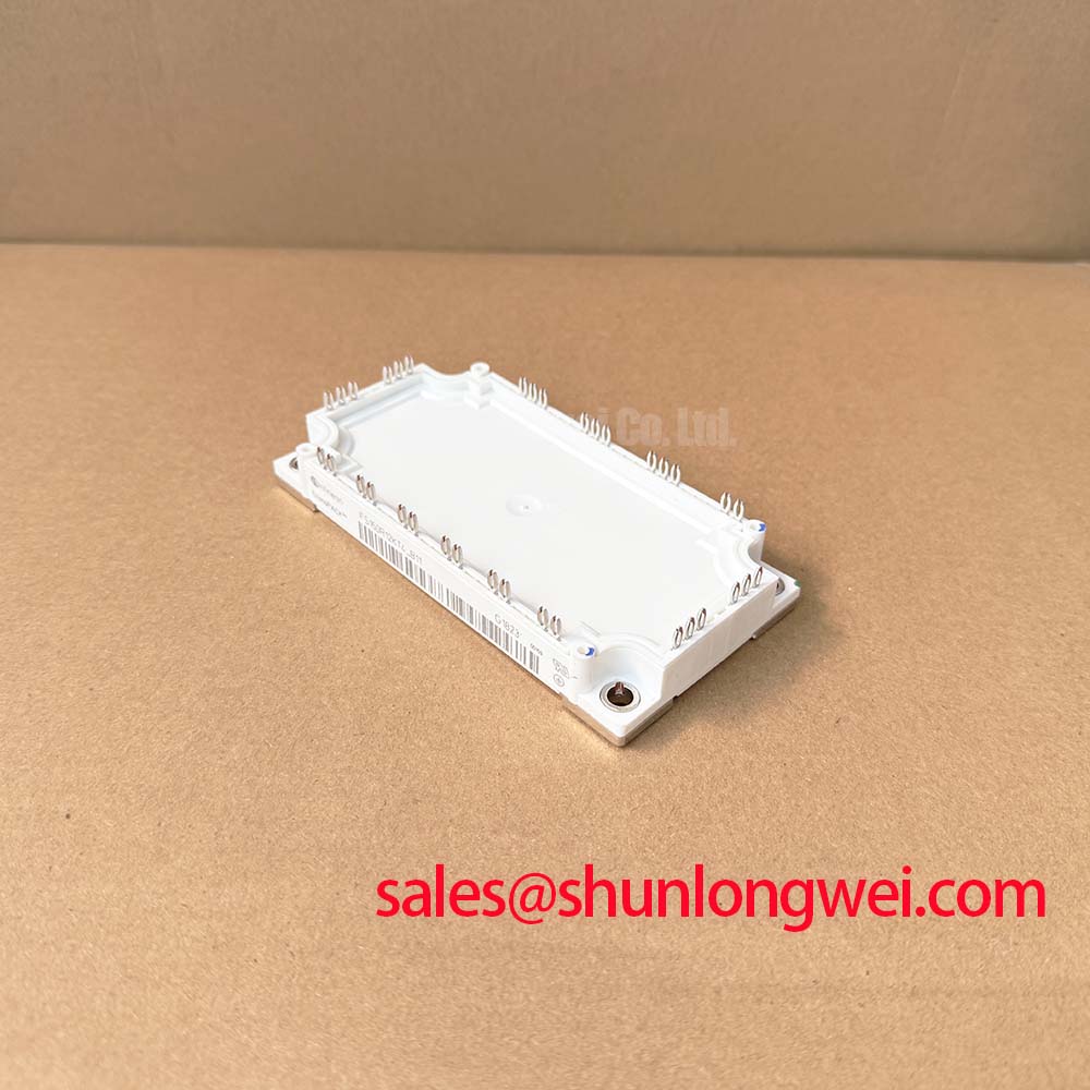
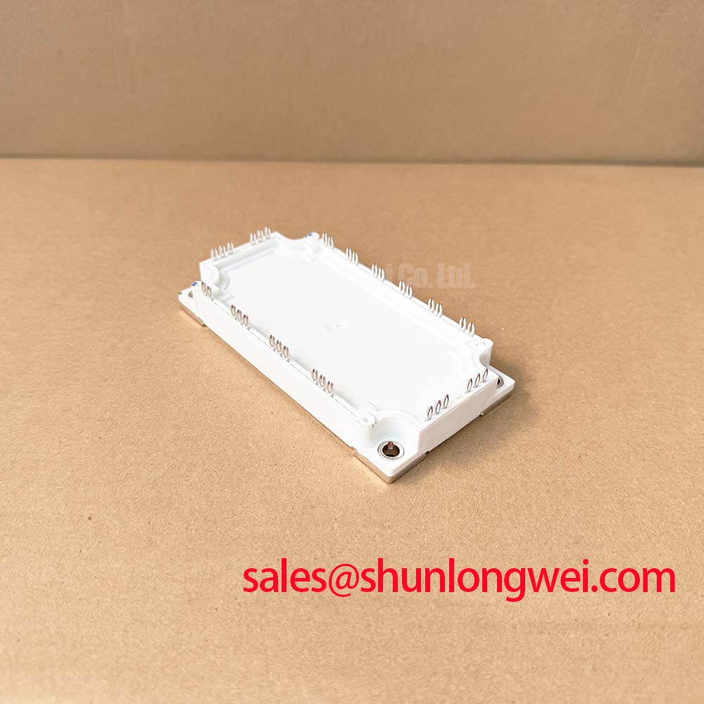
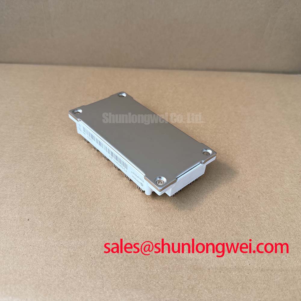
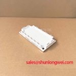
Infineon FS150R12KT4_B11 EconoPACK 3 Sixpack IGBT Module
Highlight Overview
Unique Value Proposition & High-Level Specifications
The FS150R12KT4_B11 is a highly integrated 1200V, 150A sixpack IGBT module designed for industrial power conversion systems. It is built on the robust Trench/Fieldstop IGBT4 platform with EmCon4 diodes. This design delivers exceptional switching efficiency and low conduction losses. With its integrated PressFIT contact technology and built-in NTC temperature sensor, it addresses critical assembly and thermal management challenges. For 400V AC grid applications requiring maximum thermal margins and minimal switching losses, this 1200V module is the optimal choice.
Key Parameter Table
Functional Parameter Breakdown for System Integration
| Electrical Ratings | |
|---|---|
| Collector-Emitter Voltage (VCES) | 1200 V (at Tvj = 25°C) |
| Continuous DC Collector Current (IC nom) | 150 A (at TC = 90°C) |
| Repetitive Peak Collector Current (ICRM) | 300 A |
| Total Power Dissipation (Ptot) | 750 W (per switch, TC = 25°C) |
| Gate Drive & Control | |
| Gate-Emitter Peak Voltage (VGES) | ±20 V |
| Gate Threshold Voltage (VGEth) | 5.2 V min / 5.8 V typ / 6.4 V max (at IC = 5.3 mA) |
| Gate Charge (QG) | 1.25 µC (VGE = -15 V to +15 V) |
| Internal Gate Resistor (RGint) | 5.0 Ω (at Tvj = 25°C) |
| Thermal & Mechanical Parameters | |
| Operating Junction Temperature (Tvj op) | -40°C to +150°C |
| Thermal Resistance, Junction to Case (Rth(j-c)) | 0.20 K/W max (IGBT, per switch) |
| Isolation Test Voltage (VISOL) | 2.5 kV (RMS, f = 50 Hz, t = 1 min) |
| Mounting Technology | PressFIT (Solder-less) |
Download the FS150R12KT4-B11 datasheet for detailed specifications and performance curves.
Application Scenarios & Value
Maximizing Industrial Drive Reliability and Solar Inverter Throughput
The FS150R12KT4_B11 is primarily utilized in motor control, serving as the power stage in industrial Variable Frequency Drive (VFD) topologies and high-efficiency solar inverter systems using high-power IGBT modules. In these environments, power modules must survive high thermal cycling loads and frequent overcurrent transients during startup phases. For instance, in automated manufacturing lines, a motor drive encounters significant surge currents during high-torque startup. The 300A repetitive peak collector current rating allows system designers to manage these peaks without over-specifying the module footprint.
To ensure robust operation, the gate driver must be optimized to control switching speeds. This optimization minimizes electromagnetic interference while keeping overall switching losses low. Designers can refer to the engineer's ultimate guide to IGBT modules for advanced drive stage design principles. If a solder-pin layout is preferred for existing assembly lines, the related FS150R12KT4 provides the identical electrical specification but utilizes traditional solder pins. Conversely, for lower-power systems, the FS100R12KT4_B11 offers a 100A configuration within the same EconoPACK™ 3 package footprint.
Technical & Design Deep Dive
Switching Losses Optimization and Solder-less PressFIT Integration
At the silicon level, the module leverages Trench IGBT4 technology. The trench gate structure significantly reduces the collector-emitter saturation voltage (VCE(sat)) while maintaining a positive temperature coefficient. This positive coefficient is vital for safety; it prevents thermal runaway during parallel operation. When reading technical documents, understanding parameters is essential. Designers can consult our guide on decoding IGBT datasheets to better interpret the trade-offs between conduction and switching energies. What is the primary benefit of its PressFIT design? It eliminates solder fatigue to enhance long-term system reliability.
Consider the typical VCE(sat) of 1.75V. Just like water pressure dropping across a narrow pipe, the collector-emitter saturation voltage represents the unavoidable voltage drop when the IGBT is fully on. A lower VCE(sat) acts like widening the pipe, ensuring minimal power is lost as heat during conduction. In terms of mechanical mounting, the PressFIT pins form a gas-tight, cold-welded joint. This interface behaves like a structural rivet instead of a glued surface, removing the risk of solder crack propagation under severe thermal cycling. This is a critical advantage in systems subjected to harsh vibration, ensuring a long operational lifetime.
Frequently Asked Questions
Engineering Queries Regarding PressFIT Installation and Thermal Specs
What is the primary benefit of the PressFIT connection in the FS150R12KT4_B11? It provides enhanced long-term reliability by eliminating solder fatigue and enabling a faster, solder-less manufacturing process. The gas-tight connection is highly resistant to thermal cycling and mechanical shock.
How does the positive temperature coefficient of the collector-emitter saturation voltage affect design? The positive temperature coefficient of VCE(sat) (increasing from 1.75V at 25°C to 2.10V at 150°C) forces current to distribute evenly among parallel chips. This self-balancing characteristic simplifies circuit layout and prevents localized overheating.
Why does the datasheet restrict continuous current to 50 A rms per connector pin? Although the silicon chips are rated for a nominal 150A, the physical connector pins are limited to 50 A rms. To handle the full rated current, designers must parallel multiple PCB traces and contact holes to distribute the current load safely across the pins. For verification of module integrity before installation, refer to our step-by-step tutorial on testing an IGBT module with a multimeter.
For engineers planning system upgrades or sourcing replacement modules, verify stock levels and request detailed pricing from our sales team today to secure your power electronics supply chain.