Content last revised on September 10, 2026
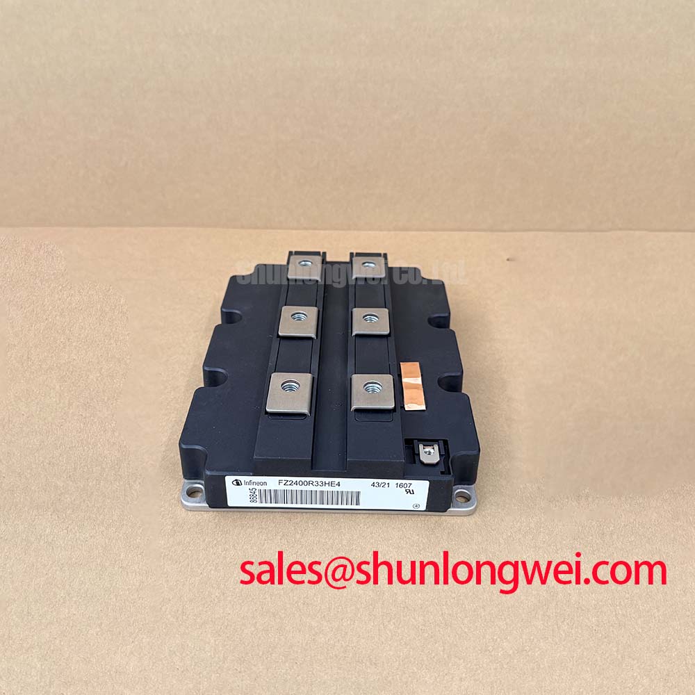
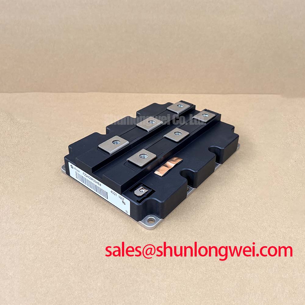
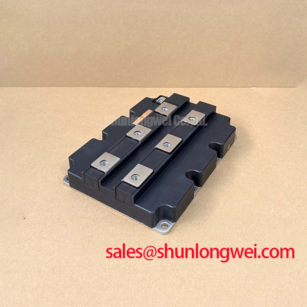
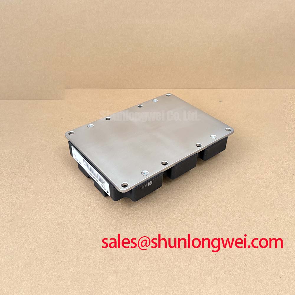
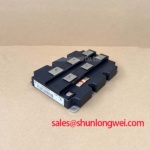
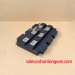
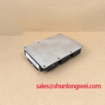
FZ2400R33HE4 Infineon 3300V 2400A High-Power IGBT Module
A high-power density Trench/Fieldstop IGBT4 module designed to maximize dynamic robustness and extend operational lifetimes in demanding medium-voltage grids.
Key Specs: 3300V | 2400A | Rth(j-c) 5.50 K/kW.
Key Benefits: Reduces conduction losses. Extends thermal cycling capability.
What is the primary benefit of its AlSiC baseplate? Enhanced thermal cycling capability by minimizing mechanical stress.
How does the trench/fieldstop technology reduce loss? By lowering collector-emitter saturation voltage under high current loads.
For traction applications demanding extreme thermal cycling resilience, this 3300V module represents the industry-leading solution.
Key Parameter Overview
Decoding the Specs for Enhanced Thermal Reliability
| Functional Group | Specification Parameter | Symbol | Value |
|---|---|---|---|
| Voltage & Current Ratings | Collector-emitter voltage | VCES | 3300 V |
| Continuous DC collector current | IC | 2400 A (TC = 105°C) | |
| Repetitive peak collector current | ICRM | 4800 A | |
| Thermal & Conduction Specs | Collector-emitter saturation voltage | VCE(sat) | 2.40 V (typ, Tvj = 25°C) |
| Thermal resistance, junction-to-case | Rth(j-c) | 5.50 K/kW (per IGBT) | |
| Maximum junction temperature | Tvj op | 150°C | |
| Mechanical & Isolation | Isolation test voltage | VISOL | 6.0 kV (RMS, f = 50 Hz) |
| Baseplate material | - | AlSiC | |
| Comparative tracking index | CTI | > 600 |
Download the FZ2400R33HE4 datasheet for detailed specifications and performance curves.
Application Scenarios & Value
Achieving System-Level Benefits in High-Frequency Power Conversion
Engineers designing electric railway traction drives and industrial motor drives face demanding thermal cycling constraints. Under rapid load variations, mechanical stress at the chip interface often causes micro-cracking and premature packaging failure. The FZ2400R33HE4 addresses this challenge directly with its aluminum silicon carbide (AlSiC) baseplate. AlSiC reduces mechanical stress by matching the expansion coefficient of silicon, extending the module's lifetime.
In high-power converters like utility-scale active frontends, minimizing parasitics is a top priority. The FZ2400R33HE4 features a low stray inductance design of 6 nH. This allows designers to control voltage overshoot without using bulky snubber circuits, improving overall system packaging density. While this module is optimized for massive 2400A loads, for systems that require the same voltage level but lower current handling, the related FZ1200R33KF2C offers a collector current of 1200A.
Technical & Design Deep Dive
A Closer Look at the Trench/Fieldstop Structure and Thermal Performance
To optimize converter design, engineers must balance conduction efficiency with robust heat dissipation. A deeper understanding of these technologies can be found in this in-depth analysis of IGBT modules. The Trench/Fieldstop IGBT4 architecture of the FZ2400R33HE4 limits conduction loss by keeping the collector-emitter saturation voltage (VCE(sat)) low.
To understand the thermal advantage, consider a mechanical analogy: think of heat flux as high-pressure water passing through a pipeline. The extremely low junction-to-case thermal resistance (Rth(j-c)) of 5.50 K/kW acts like a wide, unobstructed relief valve. It prevents heat from accumulating at the silicon die, maintaining safe operation even under overload conditions. You can read more about balancing these properties in our guide to mastering IGBT thermal management.
The integrated Emitter Controlled 4 free-wheeling diode provides soft recovery characteristics. This soft-switching behavior significantly reduces electromagnetic interference (EMI) during fast turn-off cycles. The diode's low forward voltage (VF = 2.80 V typ) matches the high switching speed of the Trench IGBT, ensuring balanced power dissipation across the entire module layout. System designers can refer to official IGBT Module guidelines to optimize gate resistors for minimizing switching loss.
Additionally, the positive temperature coefficient of the VCE(sat) serves as an automatic safety check. As the junction temperature rises, the saturation voltage increases naturally. This forces current to distribute evenly when paralleling modules, helping in preventing and diagnosing key failure modes. Designers can reference standard Thermal Resistance data to calculate specific heatsink requirements for the IHM-B package.
Frequently Asked Questions
Field Engineering Insights and Standard Operation Parameters
What is the significance of the 2100 V DC stability rating?
The DC stability value (VCE(D) = 2100 V at 100 Fit) indicates the voltage level at which the device can continuously operate while keeping cosmic radiation-induced failures under 100 failures-in-time. This metric is crucial for optimizing DC-link voltages in renewable grid converters.
How does the AlSiC baseplate improve mechanical reliability over copper?
Standard copper baseplates expand much faster than silicon under heat, creating mechanical shear stress that damages solder joints. The AlSiC composite baseplate has a coefficient of thermal expansion closely matched to the silicon die, reducing solder fatigue and doubling the module's operating lifetime.
As a global distributor of power semiconductors, we specialize in sourcing high-power solutions for demanding applications. Contact our technical sales team to request pricing, verify current stock, or obtain support for your modular converter design.