Content last revised on September 10, 2026
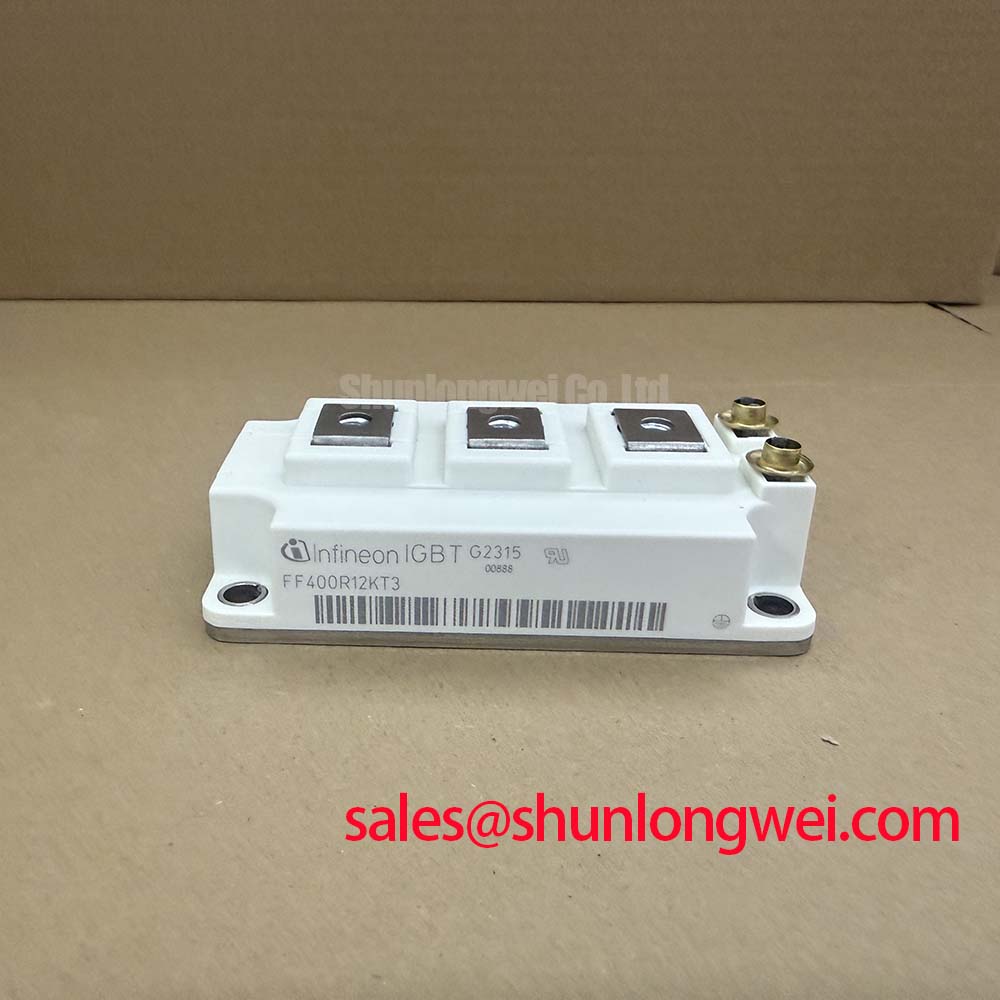
FF400R12KT3P_E Infineon 1200V 400A Dual IGBT Module with Pre-Applied TIM
The FF400R12KT3P_E from Infineon Technologies delivers an advanced power handling solution designed around a 1200V collector-emitter rating and a 400A continuous DC collector current. Featuring Trenchstop™ IGBT3 silicon and pre-applied Thermal Interface Material (TIM), this 62mm C-Series module simplifies heat sink integration while ensuring low conduction losses. What is the primary advantage of the pre-applied thermal interface material? It minimizes thermal resistance and eliminates manual grease application errors. For 400A industrial motor drives prioritizing thermal consistency and fast assembly, the 1200V FF400R12KT3P_E is the optimal choice.
Application Scenarios & Value
Eliminating Assembly Bottlenecks in High-Power Motor Drives and Converters
Engineers designing high-power industrial equipment frequently encounter thermal bottlenecks and inconsistent thermal contact caused by manual grease application. In high-demand 400A pulse-width modulation (PWM) power stages, uneven paste thickness leads to localized hot spots and early module degradation. The FF400R12KT3P_E solves this engineering challenge by incorporating factory pre-applied TIM across its isolated copper baseplate, establishing reproducible thermal bonding straight out of the box.
Key operational environments for this module include:
- Variable Frequency Drives (VFDs) and Heavy Motor Drives: Provides robust 1200V blocking capability and low saturation voltage VCE(sat) = 1.70V, suppressing operational losses during continuous torque delivery.
- Uninterruptible Power Supplies (UPS): Supports fast transient switching and high overload withstand capabilities, maintaining stable grid-to-load transitions.
- Wind Turbine Converters: Delivers high power density within a standard 62mm C-Series footprint, supporting rigorous power cycling demands.
- Solar Inverters & High-Power Converters: Facilitates efficient DC-to-AC conversion across broad ambient temperature ranges.
For system designs requiring lower current scaling in the same voltage class, the related FF300R12KT3_E provides a 300A alternative, whereas applications targeting next-generation switching dynamics may evaluate the FF400R12KT4.
Technical Deep Dive
Trenchstop™ IGBT3 Architecture & Pre-Applied TIM Thermal Dynamics
The core silicon in the FF400R12KT3P_E utilizes Infineon's field-proven Trenchstop™ IGBT3 technology combined with an Emitter Controlled HE free-wheeling diode. By pairing a trench gate structure with an internal field-stop layer, the module achieves an optimal balance between switching energy loss (Eon and Eoff) and low saturation voltage.
A crucial dynamic in module failure analysis is controlling junction temperature rise. How does the positive temperature coefficient of VCE(sat) benefit power systems? It ensures equal current sharing when paralleling IGBT modules. As operating junction temperatures approach Tvj = 125°C, the saturation voltage increases predictably, preventing current crowding across parallel legs. For an in-depth understanding of system thermal paths, engineers can review our guide on thermal resistance analysis.
Furthermore, the factory-applied TIM layer provides a predictable thermal impedance path superior to standard screen-printed thermal pastes. This layer eliminates microscopic air gaps between the module baseplate and heatsink, effectively reducing overall junction-to-heatsink Thermal Resistance and protecting the semiconductor against thermal shock during peak overload pulses.
Key Parameter Overview
Electrical, Thermal, and Mechanical Data
The table below summarizes essential engineering parameters for the FF400R12KT3P_E power module:
| Parameter | Symbol | Rated Value / Condition |
|---|---|---|
| Collector-Emitter Voltage | VCES | 1200V (Tvj = 25°C) |
| Continuous DC Collector Current | IC nom | 400A (TH = 65°C, Tvj max = 150°C) |
| Repetitive Peak Collector Current | ICRM | 800A (tp = 1 ms) |
| Gate-Emitter Peak Voltage | VGES | ±20V |
| Collector-Emitter Saturation Voltage | VCE(sat) | 1.70V typ (IC = 400A, VGE = 15V, Tvj = 25°C) |
| Internal Thermal Interface Material | TIM | Pre-applied phase-change material |
| Comparative Tracking Index | CTI | > 400 |
| Module Housing | Package | 62mm C-Series with isolated baseplate |
Download the FF400R12KT3P_E datasheet for detailed specifications and performance curves. Learn more about reading complex rating charts in our technical tutorial on decoding IGBT datasheets.
Frequently Asked Questions
Engineering Considerations for 62mm Module Integration
How does pre-applied TIM alter the heatsink mounting workflow compared to standard modules?
Pre-applied TIM eliminates the manual paste printing process on the assembly line, reducing manufacturing variation and contamination risks. Designers can mount the module directly onto a clean heatsink using recommended torque parameters (3.0 to 6.0 Nm for M6 baseplate mounting screws), achieving consistent thermal contact instantly.
What gate drive strategies best prevent parasitic turn-on in 1200V 400A topologies?
To maintain reliable switching in high di/dt conditions, use gate drivers with active Miller clamping or supply a negative turn-off gate bias (typically -8V to -15V). Maintaining short, low-inductance connections to the auxiliary emitter terminals minimizes ringing during high-current switching events. Discover more on gate driver topology optimization in our article on advanced drive topologies.
Ready to integrate the FF400R12KT3P_E into your power inverter design? Contact our engineering support team today for technical documentation, stock availability, and volume quotes tailored to your project requirements.
[