Content last revised on October 17, 2026
FZ3600R12KE3 Operational Boundaries: Controlling Commutation Turn-Off Voltage Spikes
Turn-off voltage stress must be examined together with the antiparallel freewheeling diode recovery current, the commutation path, and the DC-link structure. A fast reverse-recovery event can produce a sharp current transition, and the resulting stray inductance can raise the collector-emitter voltage above the static bus value. The practical task is to observe the switching node with a properly rated differential probe and compare the peak waveform with the voltage boundary required by the system design.
This is a Design Consideration, not an additional factory rating for the FZ3600R12KE3. Keep the high-current commutation loop compact, place the DC-link decoupling path close to the module terminals, and avoid routing the gate-return conductor through the power-current path. The PCB or laminated busbar layout should preserve suitable creepage and clearance for the working voltage, pollution environment, insulation system, and enclosure geometry selected by the equipment designer.
When the turn-off waveform shows excessive ringing, engineers should separate the possible contributors rather than changing the gate resistor without measurement. Review the probe connection, busbar joints, capacitor mounting, diode recovery behavior, and gate-loop inductance. An RC snubber or MOV-assisted overvoltage network may be evaluated as part of the protection architecture. Its clamp level, energy capability, pulse repetition performance, and coordination with the DC-link capacitor must be selected from measured switching conditions and system fault requirements.
The turn-on gate resistance can also be tuned as an Engineering Recommendation to moderate current rise and electromagnetic ringing. The correct value is system-determined: it must be established through switching tests that verify conduction loss, turn-on overshoot, diode recovery interaction, driver dissipation, and electromagnetic behavior. Infineon’s IGBT Modules Overview provides useful manufacturer-level context for evaluating module technologies, while the RCDC application note helps distinguish reverse-conducting device behavior from conventional IGBT and diode commutation paths.
For a topology review involving a lower-current branch or a physically different current requirement, the FZ1200R12KF4 can be examined as a separate Infineon module reference. It should not be treated as a drop-in substitute without checking voltage, current, terminal arrangement, gate characteristics, mechanical fit, thermal impedance, and protection coordination.
Assembly Integrity and Layout Architecture for Four-Quadrant Power Flow
Four-quadrant PCS operation reverses power direction between the battery racks and inverter link, so the module experiences repeated transitions between rectification and inversion roles. The design review should follow the actual current path in both directions. A busbar that appears acceptable during charge operation may show a different voltage drop, commutation loop, or thermal distribution during discharge and reactive-power operation.
High-side gate power integrity deserves particular attention in a floating bridge leg. Bootstrap arrangements must be sized from the selected driver’s gate-charge demand, quiescent current, refresh interval, switching duty cycle, leakage, temperature behavior, and the permitted gate-voltage droop. The FZ3600R12KE3 listing does not establish a universal bootstrap capacitor value; the value is an Engineering Calculation based on the driver data and the module’s confirmed gate-charge characteristics. Designers should verify the result during maximum duty operation and during transitions where the bootstrap supply has limited refresh time.
Dead-time must prevent direct conduction through the same bridge leg while avoiding unnecessary diode conduction that increases recovery stress and losses. This is a system timing parameter, not a fixed FZ3600R12KE3 specification. Confirm the propagation delay of both driver channels, isolation delay variation, temperature drift, fault shutdown behavior, and the measured switching waveform. A short controlled gate-drive loop with a defined return path is preferable to a long shared control trace that allows power-current noise to enter the driver reference.
For the front-end or auxiliary rectification stage, engineers may review the FD300R12KE3 as a separate complementary product reference. The relationship between that device and the FZ3600R12KE3 must be assessed at the topology level, including current sharing, control timing, thermal placement, fault isolation, and the electrical requirements of the particular PCS.
Thermal cycling during peak shaving is strongly influenced by current waveform, cooling impedance, clamping uniformity, switching frequency, overload duration, and control strategy. A Design Consideration is to compare measured case temperatures at several operating quadrants rather than relying on one steady-state operating point. The module base, thermal interface, heatsink, and airflow or liquid-cooling arrangement should be treated as one mechanical and thermal assembly.
Field Diagnostics and Commissioning: Mechanical Stress Control in FZ3600R12KE3 Topologies
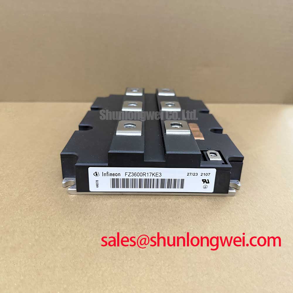
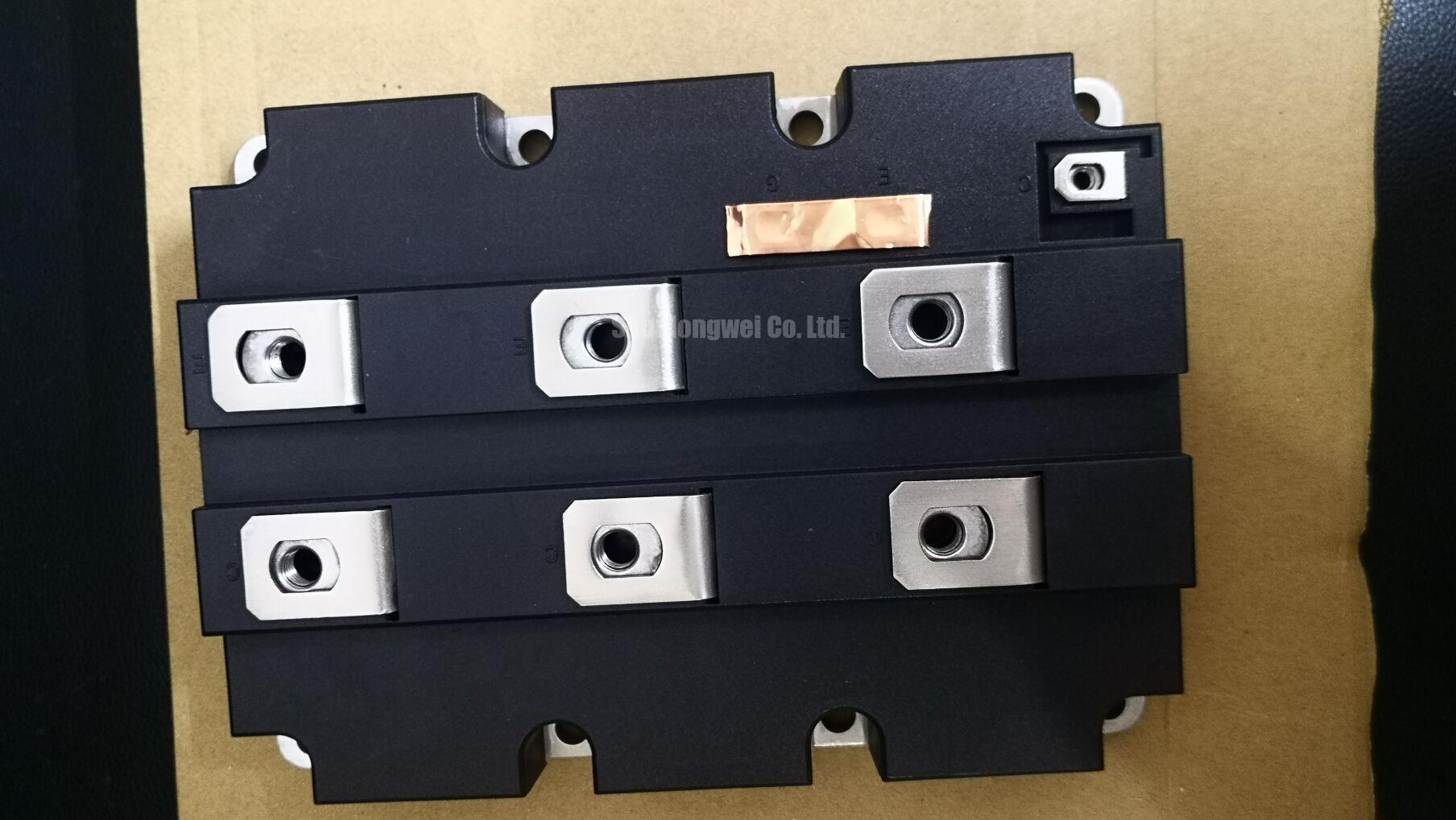
Mechanical commissioning begins at the power terminals because incorrect thread engagement, tilted washers, or misaligned busbars can transfer levering forces into the internal copper connections. Before tightening, place the module and busbar assembly in its natural position, confirm that the mating surfaces sit flat, and ensure that the fastener does not bottom out before applying useful clamping force.
Use the fastener, washer, terminal design, and installation instructions specified for the equipment assembly. A general mounting torque value must not be presented as an official FZ3600R12KE3 rating. The correct torque is a Design Consideration governed by the bolt specification, thread condition, contact materials, washer system, and the module manufacturer’s mechanical documentation. Check the result with a calibrated tool and record the assembly condition for later maintenance comparison.
🔧 Field Alert: Do not force a misaligned busbar into position by tightening the terminal hardware, because the resulting mechanical load can remain after the electrical connection appears secure.
The thermal interface should be spread as a uniform, controlled layer appropriate to the selected heatsink surface and assembly method. Excess compound can increase cleanup risk and contaminate nearby insulation, while insufficient coverage can leave localized thermal resistance. The pressure system should distribute force across the base without creating a concentrated load at one corner. When disc springs or other compliant washers are used, inspect their orientation, seating, and compression condition according to the equipment assembly specification.
During field replacement, compare the terminal spacing, base dimensions, mounting points, auxiliary terminals, gate connections, and cooling interface with the removed device before energization. A matching electrical rating alone does not establish mechanical or control compatibility. After installation, check for unintended continuity between the power circuit, gate circuit, and mounting structure using an approved procedure for the equipment’s insulation system. Reconnect control and power cabling only after stored energy has been discharged and the isolation state has been verified.
FZ3600R12KE3 Circuit Protection and DC-Bus Reliability
The 1200.0 V rating of the FZ3600R12KE3 is an Official Specification, but it does not by itself define the allowable operating bus voltage for every PCS installation. The DC-link protection design must account for switching overshoot, regenerative events, fault interruption, capacitor tolerance, control delay, temperature, insulation coordination, and the transient energy available from the battery system.
At elevated sites, atmospheric effects and terrestrial neutron exposure may be included in a formal reliability assessment, particularly when a converter operates at a high DC-bus voltage. SEB and FIT values must come from an applicable manufacturer reliability source, qualification report, or recognized methodology for the actual device technology and operating conditions. They should not be inferred from the 1200.0 V label or converted into a universal altitude derating rule.
The practical commissioning response is to record the highest measured switching-node voltage during charge, discharge, reactive-power operation, startup, controlled shutdown, and fault clearing. Compare those measurements with the system’s validated protection limits. Verify the response of MOVs, active clamps, snubbers, semiconductor fuses, desaturation protection, overcurrent detection, and DC-link discharge circuits as a coordinated protection system. The device-level choice and the PCS control response must remain aligned.
Use the Precision Gate Drive Design reference when reviewing gate-loop behavior, driver isolation, shutdown sequencing, and switching-test practice. The final verification should include thermal measurements, gate-emitter waveform integrity, collector-emitter transient capture, protection timing, and a controlled return to service after the electrical and mechanical checks are complete.