

Content last revised on September 13, 2026
Suppressing Pixel Jitter & Horizontal White Lines Induced by Adjacent 400V Motor Drives
When a service terminal is positioned close to a variable frequency drive, pixel jitter, rolling brightness disturbance, or horizontal white bands can be introduced through the signal cable route, a shared reference path, or conducted noise entering the display power path. Begin by observing whether the symptom changes when the nearby motor drive is stopped, when the display cable is gently supported, or when the panel is supplied from a known stable service source. These checks help separate a display-path disturbance from a controller, cable, or surrounding installation issue.
For the AUO G156XW01 V3, the system integrator should verify the original cable shielding arrangement and connector pin assignment before reconnecting the panel. A Design Consideration is to maintain a continuous shield termination where the machine cable design supports it, especially where the display cable crosses motor leads, braking conductors, contactors, or inverter output wiring. Common-mode suppression can also be evaluated on the affected cable route, with the final selection verified by observing the panel under actual switching conditions.
Do not treat a moving noise band as proof that the LCD module itself has failed. A poor frame ground, an intermittently seated connector, a cable shield left floating after maintenance, or supply ripple can produce similar visible behavior. Compare the affected path with a known-good signal path using appropriate service instrumentation, then verify whether the symptom remains after the original routing and grounding scheme have been restored.
⚠️ Field Alert: Isolate system power and confirm stored energy has discharged before unplugging or reconnecting the display interface, because live connector movement can expose signal pins to unintended level transitions.
Backlight brightness decline should also be assessed through the actual equipment history and the original panel documentation rather than by applying a generic operating-life figure to this specific model. If the display image remains stable while luminance is weak, check the host-side backlight drive and its supply path before assigning the symptom to the panel. For broader installation and environmental test practices, engineers can use Industrial Display & HMI Solutions as a practical reference point.
VESA vs. JEIDA Data Mapping Alignment & Even/Odd Channel Signal Integrity
A panel that powers with an illuminated but split, color-shifted, repeated, or scrambled image requires a disciplined interface check. Confirm the original equipment’s display controller configuration, the cable part number, and the documented mapping convention before replacing the module. VESA and JEIDA mapping are controller-to-panel data conventions, not interchangeable assumptions; an apparent screen defect can arise when the controller output configuration and panel expectation do not align.
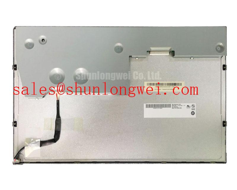
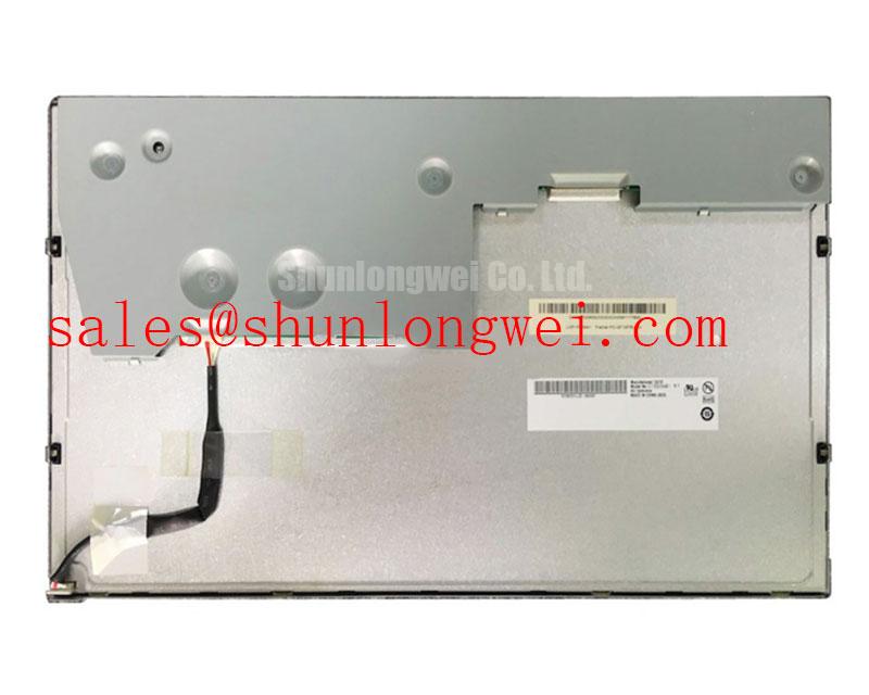
The factory context provided for G156XW01 V3 identifies the product as an AUO TFT-LCD display module, but it does not provide an interface voltage, pinout, mapping selection, or timing table. The system integrator should verify the required supply voltage from the original panel documentation. They should also verify the interface standard, connector orientation, lane assignment, and power-on sequence against the removed panel and host controller documentation.
Signal integrity is a Design Consideration whenever the display path has been disturbed during service. The relevant principle is to preserve the original controlled differential routing and reference continuity so that even and odd data channels arrive coherently at the panel connector. If a fault appears only after a cable replacement or harness reroute, inspect for pin displacement, damaged latch features, crushed sections, or an unintended change in cable length and shield termination. Oscilloscope comparison with a known-good path can help determine whether the transmitter, cable assembly, or panel-side connection deserves further investigation.
Where a repair team is evaluating another panel, LMS700KF01-001 can be reviewed as a separate display option. It must not be treated as a direct substitute without confirming the original equipment’s mechanical envelope, display interface, electrical requirements, controller timing, and firmware configuration.
Grayscale Inversion Mitigation & Optimal Viewing Direction Alignment
Before interpreting a washed-out image as a failed display, inspect it from the normal operator position and then from above, below, and both sides. Viewing-angle-related tonal changes, a controller gamma setting, a surface contamination issue, a weak backlight, and an incorrect image data mapping can all present as poor grayscale or contrast. The observed behavior must be compared with the original panel specification and the known-good machine display where one is available.
The available verified specification context does not establish the liquid-crystal mode, viewing-angle values, surface treatment, or optical construction of the G156XW01 V3. Those attributes should therefore be confirmed from the original AUO documentation rather than inferred from the product family name or from the appearance of another panel. This is particularly important when a high-voltage substation protection terminal is viewed from a fixed console position, where the enclosure angle and operator sightline can affect perceived contrast.
In a SCADA dispatch console, evaluate the display under the site’s normal ambient illumination after the cable and controller configuration have been verified. Reflections across the active area can conceal faint text or make grayscale steps appear uneven. A Design Consideration is to examine the panel surface, bezel fit, and enclosure window as a complete optical path, then determine whether the issue remains when the display is tested in controlled lighting. Avoid assigning a particular anti-glare treatment or viewing cone to this model without the relevant factory document.
Clock quality and receiver timing also belong in the diagnostic path when image corruption changes with temperature or controller load. The useful principle is to preserve timing margin across the full host system condition, while the controller, cable assembly, and validated panel documentation determine the acceptable operating boundaries. If display artifacts are intermittent, capture the signal behavior against a known-good channel rather than assuming that a visible line corresponds to one isolated hardware cause.
Mitigating Gray-to-Gray Response Time Escalation during Cold-Start Machine Power-Up
For a cold-start complaint, first distinguish between an image that is present but slow to update, an image that is dim, and a screen that has no valid image at all. Observe the panel during startup, after the terminal reaches normal cabinet temperature, and after reseating the original cable assembly with power removed. This creates a more useful fault record than treating every low-temperature display complaint as a liquid-crystal response issue.
Temperature can influence perceived motion response and contrast in LCD systems, while the actual behavior of the G156XW01 V3 must be assessed against its original factory temperature specification. The supplied verified context does not state an operating-temperature range, gray-to-gray response time, backlight dimming method, or perimeter seal construction. Engineers should obtain those model-specific limits from the original panel documentation before defining acceptance criteria for a protection terminal or dispatch-console retrofit.
If flicker is reported during machine startup, inspect the host power supply, display cable seating, backlight-driver path, and controller configuration. PWM behavior, if used by the equipment design, should be verified from the original system documentation and observed under the machine’s real dimming conditions. The applicable Design Consideration is to confirm stable visual performance at the intended brightness settings without imposing unsupported dimming values on the panel itself.
For equipment exposed to seasonal cabinet temperatures, keep the panel evaluation focused on measurable conditions: startup behavior, image stability, brightness consistency, connector integrity, and controller output quality. This method supports a defensible repair decision while respecting the documented boundaries of the AUO display module and the host system that drives it.