

Content last revised on October 25, 2026
Chassis M3 Fastener Torque Sizing to Limit Optical Mura Defects
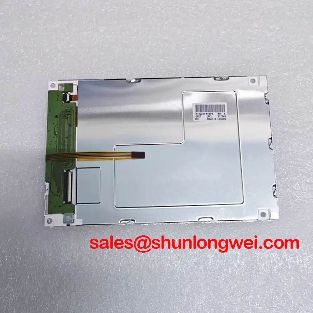
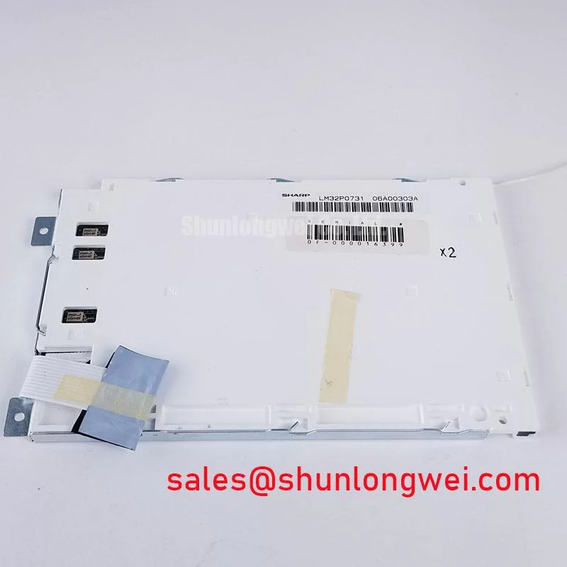
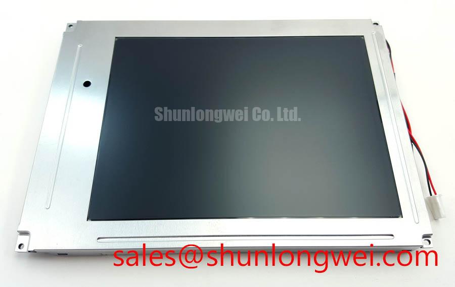
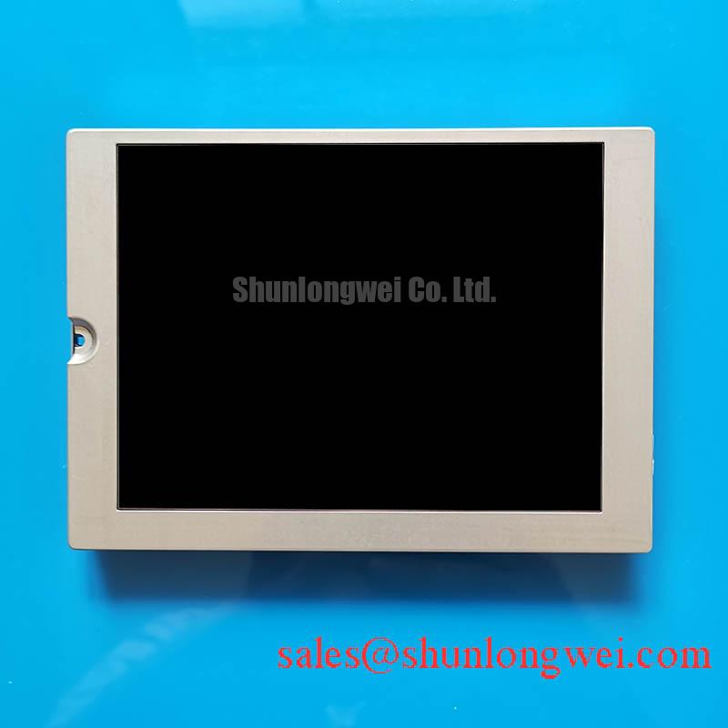
When a clinical display shows a dark corner, unstable grayscale, or intermittent image data, isolate the panel from the host system before changing the display module. Check the chassis pressure around the bezel, confirm that the panel connector is fully seated after power removal, and compare the displayed image with a known good signal path. The KCG057QV1DB-G00 is a Kyocera color STN passive matrix LCD module used in industrial display integration.
Because the available product information does not establish a complete electrical interface definition, the system integrator should verify the original panel documentation for supply voltage, connector assignment, signal protocol, timing, backlight arrangement, and mechanical drawing before installation. Kyocera’s display information provides useful background for evaluating panel technology and application requirements: Kyocera Display Technologies.
Localized bezel pressure should be investigated before adjusting image parameters. A display module can show uneven luminance or dark-field mura when the chassis, bezel, or mounting frame applies nonuniform mechanical loading. Torque for any M3 chassis fasteners should be selected for the specific assembly rather than treated as a universal panel installation value. Final torque depends on the frame material, thread engagement, washer arrangement, screw condition, and the panel manufacturer’s mechanical drawing.
Use a cross-pattern tightening sequence so that the bezel settles progressively rather than pulling one edge into contact first. During service, inspect whether a symptom follows the frame position when the module is gently repositioned without applying pressure to the active area. That observation helps separate chassis loading from a display drive or backlight issue. Designers should also maintain even support around the outer envelope and avoid concentrated contact near the viewing area.
For high speed display links, controlled routing is a separate system-level requirement. A 100 Ω ± 10% differential impedance and a skew target of 50 ps or less may be used as a general Design Consideration for suitable differential interfaces in electrically noisy equipment. These values are not confirmed factory parameters for the KCG057QV1DB-G00. The actual interface type, pair assignment, termination, and timing limits must come from the host and panel documentation.
⚠️ Field Alert: Disconnect system power before removing or inserting the panel cable, and prevent bezel fasteners from loading the active display area.
Surface Anti Glare and Anti Reflective Treatment for Ambient Readability
Ambient light assessment should be performed with the panel installed in its actual bezel and viewing direction, not only on a loose bench. Reflections from surgical navigation consoles, ultrasound carts, or operator panels can make a healthy display appear low contrast. Surface treatment, cover glass, enclosure geometry, and room lighting all influence the result.
The KCG057QV1DB-G00 is a color STN passive matrix display module, but the available information does not confirm an AG coating, an AR coating, or a viewing angle specification. Those features must not be assigned to this model without the applicable Kyocera drawing or datasheet. When comparing a replacement, engineers should evaluate grayscale stability from the required viewing positions rather than relying only on a nominal diagonal viewing angle.
TN panels can show grayscale inversion or tonal changes when viewed away from the preferred axis. IPS and MVA technologies are often evaluated where more symmetrical viewing behavior is required, but any change in display technology must be evaluated against the original equipment’s electrical, mechanical, and optical requirements. A stated viewing cone of 85°/85°/85°/85° should therefore be treated as a comparison requirement only when it is confirmed in the relevant panel documentation.
| Evaluation item | KCG057QV1DB-G00 | LQ057Q3DC03 reference |
|---|---|---|
| Manufacturer | Kyocera | Confirm from applicable documentation |
| Product category | Industrial LCD module | Evaluate suitability for the intended application |
| Display construction | Color STN passive matrix LCD module | Confirm display technology and optical mode |
| Mechanical and electrical replacement data | Match against the original equipment documentation | LQ057Q3DC03; compatibility is not established |
For optical evaluation, compare white uniformity, black level, grayscale transitions, and readability under the equipment’s real lighting. Background on optical diffusion can be reviewed through Optical Diffusers. The referenced optical principles are industry information and do not establish construction details inside this Kyocera module.
Industrial EMI Noise Immunity, Chassis Shielding Continuity and Common Mode Suppression
Pixel jitter and horizontal noise bands should be traced through the complete display path, including the host graphics output, panel cable, chassis bonding, and nearby motor drive wiring. In equipment containing variable frequency drives or servo amplifiers, cable placement and shield termination can have more influence than the panel label alone.
Where the host uses a differential display interface, route the pair as a controlled differential structure with consistent reference to the chassis or signal return selected by the system designer. A 360 degree shield termination can reduce the exposed pigtail area at the enclosure boundary, but the correct bonding method depends on the equipment grounding architecture and safety design. Common mode ferrite components may be evaluated when conducted or radiated interference is observed, with their impedance behavior checked across the disturbance frequency range.
Do not assume that an LVDS cable can replace a TTL cable, or that a connector with a similar appearance has the same pinout. The integrator should verify protocol, pair polarity where applicable, clock arrangement, data mapping, enable signals, and power sequencing against the original equipment documentation. An oscilloscope comparison at the host output and panel input can help identify whether the disturbance is generated before the cable, coupled along the route, or introduced at the connector.
Clock jitter and data hold behavior must remain within the limits of the selected transmitter, receiver, and panel interface across the equipment temperature range. These are system timing requirements rather than confirmed KCG057QV1DB-G00 factory values. Panel replacement should proceed only after the signal format and timing relationship have been matched.
Aluminum Heat Spreader Sizing and Thermal Interface Placement Along Narrow Display Edges
Thermal evaluation should begin by locating the actual hot region with the display operating in its installed enclosure. Edge temperatures can be affected by the backlight assembly, nearby power electronics, enclosure airflow, and the way the chassis contacts the module. An aluminum spreader rail may help distribute heat when it is mechanically compatible, electrically safe, and thermally coupled without stressing the display.
Use a broad, even interface where the mechanical design permits it, while keeping pressure away from the active area and avoiding contact with flexible circuits or exposed conductors. The spreader size, interface material, contact pressure, and enclosure ventilation are system design variables. They should be validated through temperature mapping under the intended brightness, ambient condition, and duty cycle rather than selected from a generic panel rule.
Direct sunlight creates a separate readability problem. A contrast ratio above 500:1 at 50,000 lux, if required by the application, would be an application acceptance target, not an established specification for this Kyocera model. The evaluation should include reflected glare, black-level lift, white saturation, grayscale visibility, and any color shift caused by the viewing angle. Anti glare treatment can reduce specular reflection, while anti reflective treatment may improve optical transmission, but the suitable combination depends on the cover window and enclosure design.
Backlight longevity should be assessed from the complete display assembly and its operating conditions. Do not assign L70 or B50 lifetime values to the KCG057QV1DB-G00 without a manufacturer source for the exact configuration. For broader enclosure and reliability planning, engineers can consult Industrial Display & HMI Solutions. If evaluated for a surgical or ultrasound diagnostic display, the module must meet the equipment’s intended imaging requirements; final acceptance should also confirm image uniformity, connector retention, thermal behavior, and signal stability after installation in the production chassis.