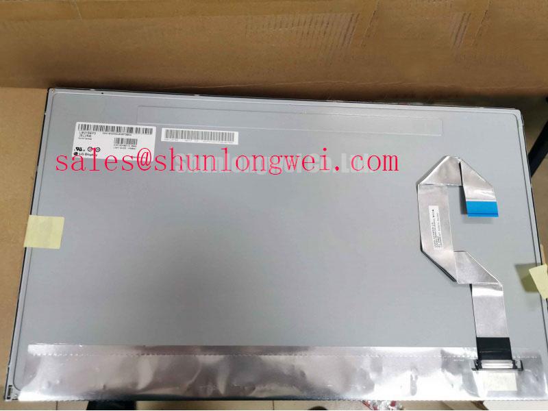
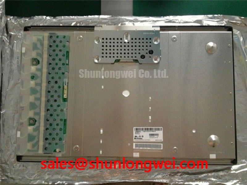


Content last revised on October 14, 2026
LM260WU2-SLA1 Display Replacement Compatibility Checks
- Record the failed console symptom before removing the display, including black screen, dim image, split image, flicker, or residual image.
- Check the panel connector, flexible cable seating, latch condition, and cable bend path with system power isolated.
- Compare the replacement panel’s mechanical envelope and mounting points with the installed assembly before applying power.
- Confirm the host controller’s video mapping, logic supply requirement, backlight architecture, and power sequencing from the original equipment documentation.
The LM260WU2-SLA1 is an LG Display TFT LCD active matrix color display module. For industrial HMI and LCD replacement evaluation, its electrical ratings, interface assignment, optical data, and mechanical dimensions must be matched to the original panel documentation before installation.
| Manufacturer | LG Display |
| Model | LM260WU2-SLA1 |
| Product category | LCD Display Panel |
| Panel construction | TFT-LCD Active Matrix Color Display Module |
For a high-voltage substation protection or SCADA dispatch console, replacement work should begin with interface compatibility rather than visual appearance alone. A panel that fits the bezel can still produce a white screen, unstable image, incorrect color order, or intermittent operation when the host timing, data mapping, power rise profile, or backlight control does not correspond with the installed display assembly.
Constant Luminance Output Control and L70/B50 LED Lumen-Maintenance Verification
Local heat concentration along the narrow edges of an LCD can create uneven optical aging, especially where the display frame, backlight assembly, and cabinet airflow restrict heat dissipation. A suitable aluminum heat spreader rail may be evaluated as a Design Consideration when it can contact the intended mechanical structure without stressing the glass, blocking the optical path, or shorting exposed conductors.
An LED backlight configuration or a manufacturer-approved L70/B50 lifetime value should not be assumed for the LM260WU2-SLA1 without supporting documentation. The installed console should therefore be inspected to identify whether its backlight uses an LED driver or another architecture before selecting a brightness-control method. If an LED driver is present, the system engineer can evaluate PWM behavior for visible flicker, acoustic noise, and linear brightness response. A practical bench check is to compare several duty-cycle settings with a photometer and oscilloscope while observing the display at normal operating temperature.
Do not treat a stated brightness setting as proof of long-term lumen-maintenance performance. L70/B50 describes the time at which 50% of the population is expected to fall below 70% of initial light output; it does not mean half brightness. Such claims require a defined test method, thermal condition, drive current, and source. The relevant system verification should correlate the actual backlight temperature with brightness uniformity and controller behavior. Optical diffusion is discussed in Diffuser (Optics), while broader industrial display considerations are available in Kyocera Industrial TFT-LCD Display Technologies.
For static SCADA screens, use the host application’s screen-rotation, dimming, or idle-display functions where available. These are system-level measures for reducing image retention risk; they are not a specification of the LM260WU2-SLA1 itself.
Dual-Channel CCFL High-Voltage Resonant Inverter Striking Voltage and Ignition Debugging
The replacement workflow must first identify the backlight technology in the original console. Do not assume a CCFL or LED configuration from the model name alone, and do not connect a CCFL inverter to the panel without matching the original assembly documentation and connector arrangement.
Where the equipment uses a dual-channel CCFL inverter, ignition behavior should be checked at the inverter output using an instrument and probe rated for the circuit’s high-voltage waveform. Cold-start difficulty, uneven illumination, or audible inverter noise can involve lamp condition, transformer balance, cable routing, connector contact, or control-loop loading. These symptoms should be compared between channels rather than assigned to one cause without measurement.
Where the equipment instead uses a constant-current LED driver, the diagnostic path changes completely. Inspect enable control, current regulation, dimming input, thermal protection response, and the relationship between the driver output and the panel’s backlight connector. A claimed 1000:1 PWM range or a specified half-life must come from the actual driver and panel documentation, not from the model name.
Video integrity must be checked separately from backlight ignition. Confirm the transmitter clock, data hold relationship, and signal behavior at the panel connector across the equipment’s intended temperature range. If the console uses LVDS, verify lane order and polarity against the known-good assembly. If it uses another interface, the replacement harness and controller must be matched to that interface rather than adapted by appearance alone.
⚠️ Field Alert: Isolate power before inserting or removing the panel cable because an energized connector can expose signal and backlight circuits to avoidable contact transients.
Thermal Cycling Degradation of Polarizer Adhesives and Sealant Gasket Integrity
Temperature changes affect the complete display assembly, including polarizer adhesion, perimeter sealing, connector retention, bezel pressure, and the mechanical relationship between the glass and its mounting frame. At sub-zero temperature, liquid-crystal response can become slower, so an operator may observe motion blur or gray-level trailing even when the input video remains stable.
For equipment exposed to cold starts, the system integrator should measure image response during a controlled temperature transition and compare several gray-to-gray transitions rather than relying on a single moving graphic. Any heater or cabinet temperature-control method must be treated as a system accessory requiring its own safety, control, and condensation assessment. It should not be assumed to be part of the LM260WU2-SLA1 module.
Thermal cycling can also reveal mechanical stress that is not visible at room temperature. Inspect the perimeter for pressure marks, nonuniform darkening, edge leakage, or changes that follow cabinet warm-up. Optical bonding, if present in the equipment assembly, should be evaluated for moisture entry, trapped contamination, and adhesion changes at the enclosure level. A specific bonding method, gasket compound, or environmental sealing grade should not be assumed without supporting documentation.
Mounting should allow the panel to sit evenly without twisting the frame. Excessive fastener force, uneven bezel contact, or a cable folded against a sharp edge can convert cabinet vibration and thermal expansion into connector intermittency. Engineers evaluating long-term HMI service can use the Industrial Display & HMI Solutions reference as a broader framework for enclosure, vibration, and environmental integration decisions.
VESA versus JEIDA Data Mapping Alignment and Even/Odd Channel Signal Integrity
Split-screen images, inverted colors, missing columns, or a white display commonly direct attention to data mapping and power sequencing. Before changing the controller, compare the installed cable pinout, lane order, clock polarity, and even/odd channel assignment with the replacement configuration. VESA and JEIDA mapping are not interchangeable assumptions; the host transmitter and panel receiver must use the same mapping convention.
The logic supply requirement must be taken from the original panel documentation and measured at the panel connector during startup. Do not select between possible supply values by visual similarity or by connector fit. Observe the supply rise, enable relationship, reset behavior, and discharge after power removal. A white screen during startup may involve missing initialization, incorrect mapping, missing video data, or an invalid power sequence, so the complete signal path should be checked with a known-good controller or reference display where available.
Differential routing should preserve pair symmetry, controlled return paths, and connector contact integrity. The system designer determines the appropriate characteristic impedance and termination arrangement from the transmitter, cable, and receiver requirements. Oscilloscope checks should compare clock and data quality at the panel end, not only at the controller output, because flex-cable routing, connector wear, and cabinet interference can alter the received waveform.
Flexible printed cables require a controlled bend path with no repeated movement at the connector latch. During replacement, inspect for whitening, creasing, exposed copper, contamination, and partial insertion. A mechanically secure latch does not by itself prove electrical continuity across every contact. For a different panel size or resolution class, engineers can review LM190E08-TLJ7 as a separate display option, but its interface, dimensions, timing, and optical characteristics require an independent compatibility review.