

Content last revised on October 17, 2026
Radiated Emissions Evaluation and Grounding Considerations
When pixel jitter or horizontal bands appear near a variable-frequency motor drive, compare the display image with the drive disabled and enabled under controlled operating conditions. Check whether the disturbance changes with motor switching, cable routing, or panel installation. This helps distinguish a signal-integrity or coupling problem from a panel image defect without treating the symptom as proof of a single cause.
Design Consideration: Keep high-current motor and switching paths physically separated from display signal wiring, and avoid unnecessary signal-cable loops. Where the host uses a shielded display cable, assess its termination and chassis bonding as part of the complete equipment design; a panel alone does not establish CISPR Class A or Class B compliance. Common-mode ferrites or multi-point bonding should be evaluated in the assembled system, because their effect depends on cable construction, grounding, and enclosure layout.
Do not assume this model accepts LVDS or TTL signaling, or a particular backlight dimming method, from its product category alone. Before connecting it, match the host interface, pin assignment, supply requirements, and startup sequence to the panel documentation. The Sharp Devices Europe Industrial Display Solutions site provides manufacturer-level industrial display context, while system-level emissions testing remains specific to the assembled equipment.
Dynamic Contrast and Temperature Evaluation
Assess grayscale and viewing-angle behavior with the panel mounted in its intended orientation and viewed from the operator’s normal position. Use a consistent set of dark, mid-gray, and bright test fields, and compare the image across the screen rather than judging contrast from a single center point. Changes in apparent contrast can arise from viewing angle, ambient reflections, host image settings, or panel characteristics.
The available product identity does not establish whether this module uses TN, IPS, or MVA technology, nor does it state a viewing cone, anti-glare treatment, dynamic contrast ratio, or temperature range. Those properties should not be inferred from the model category. For machine-tool HMI evaluation, confirm the required viewing orientation, ambient-light readability, and optical surface against the actual panel documentation and enclosure conditions.
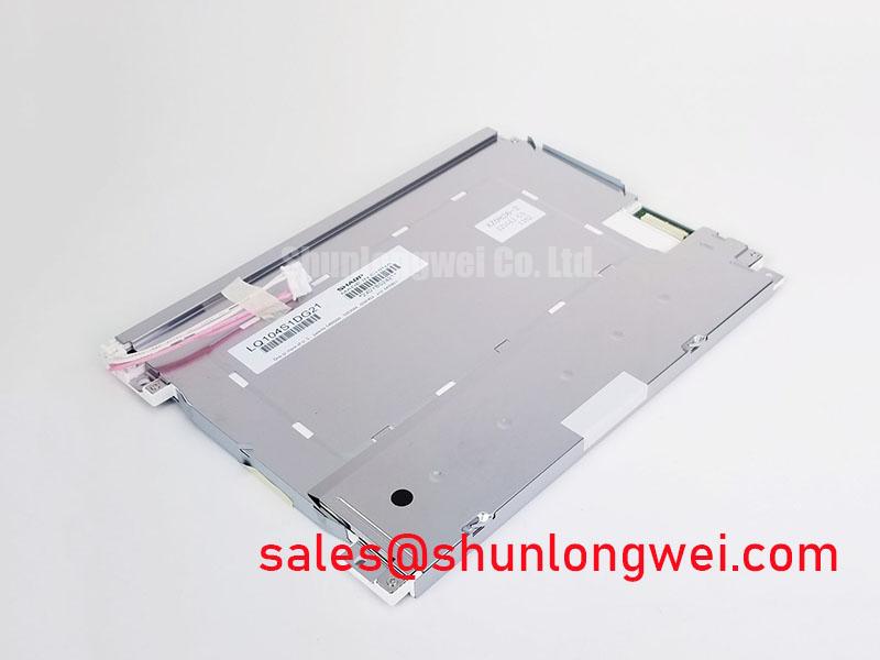
| Item | LQ104S1DG21 | LQ104S1DG61 |
|---|---|---|
| Manufacturer | Sharp | Sharp |
| Identified product type | TFT-LCD active-matrix color display module | Consult product documentation |
| Electrical and optical comparison | Consult product documentation | Consult product documentation |
The LQ104S1DG61 can be reviewed as a same-family reference, but its model designation alone does not establish a drop-in replacement. Compare connector pinout, interface signaling, timing, mounting, viewing characteristics, and backlight requirements before substitution. For general background on display interfaces and selection, see The Ultimate Guide to Industrial TFT LCD Technology.
Preventing Frame Lag and Image Smearing in Cold and Outdoor Industrial Facilities
Evaluate motion response at the actual operating temperature rather than extrapolating from a room-temperature bench check. Liquid-crystal response can change with temperature, so moving text or a scrolling test pattern may appear different in a cold environment than during initial inspection. Record the panel temperature and host refresh conditions when comparing results.
No operating-temperature range, gray-to-gray response time, or environmental sealing rating is established by the supplied product baseline. Do not treat the often-quoted industrial temperature span of −30°C to +85°C as a specification for this model. For a factory automation machine-tool terminal, confirm the equipment’s temperature exposure and warm-up conditions against the panel’s own documentation. Inspect the perimeter and mounting interface for physical damage, but do not infer sealant composition or environmental protection from appearance.
When evaluating dimming or flicker, verify the host’s backlight-control method and observe the screen under the intended operating conditions. A PWM frequency or duty-cycle range cannot be assigned to this panel without its backlight specification. Bench tip: Disconnect power before handling the display cable, use ESD precautions, and engage the connector evenly to avoid damaging its contacts.
Backlight Luminance and LED Lifetime Verification
Check luminance uniformity after the display has reached a stable operating state, using the same test image, viewing geometry, and ambient lighting for each comparison. Inspect the center and edges for visible variation, and note whether the pattern changes with host brightness settings or enclosure temperature. These observations help separate an optical presentation issue from a changing input image or backlight-control condition.
The identified product type does not confirm the backlight source, rated luminance, lifetime, L70/B50 value, or permissible drive current. Consequently, a stated LED lifetime such as 50,000 hours to 50% brightness would not be a substantiated specification for the LQ104S1DG21. Use the documented backlight requirements when checking the host driver, and assess heat spreading as a system-level design consideration rather than assuming a particular internal optical material or panel construction.
The LQ10D213 is a related display-solution reference for evaluating the broader power topology; its presence does not establish compatibility with this panel. Confirm driver output, control signals, connector mapping, and panel requirements as a complete interface set before integration.