Content last revised on November 5, 2026
Polarizer Delamination Bubble Mitigation and Optical Retardation Film Inspection under Workshop Lighting
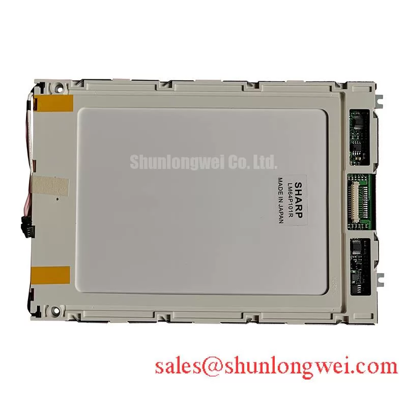
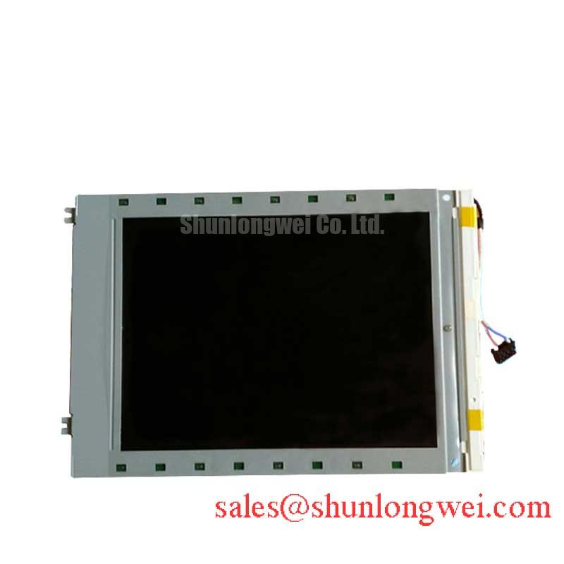
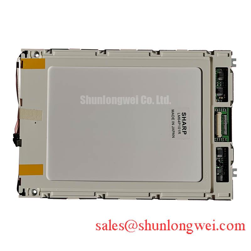
The LM64K10 is a Sharp monochrome passive matrix LCD panel. During replacement assessment, compare the complete panel marking, connector orientation and mounting arrangement with the original assembly. Electrical ratings, interface assignments, dimensions and backlight operating conditions: consult the original model datasheet before connecting a replacement.
Move the inspection light across the viewing surface at a shallow angle and record whether each apparent bubble remains fixed relative to the glass. As a Design Consideration, surface reflections, trapped contamination and separation within an optical stack can produce different appearances as illumination changes. Photograph suspect areas from a repeatable position, keeping exposure and panel orientation consistent so that automatic camera adjustments do not obscure the comparison.
Display uniform backgrounds and inspect the centre, edges and corners from the intended operator position. A local contrast patch deserves comparison across several patterns: a mark visible without power suggests a different investigation from a defect that follows displayed content. For monochrome inspection, assess background tint and contrast uniformity alongside brightness; a bright image alone does not establish readable text or consistent pixel modulation.
As a Design Consideration, heat and ultraviolet exposure can contribute to polarizer discoloration and adhesive deterioration. Iodine chemistry, transflective construction and a particular retardation film arrangement should only enter the repair specification when the panel documentation establishes them. Do not peel an optical layer as an exploratory test: changing its orientation or replacing it with an unmatched film can alter the useful viewing characteristics.
Compare ambient light readability with enclosure glazing installed, because reflections from the cover can conceal otherwise acceptable contrast. At low temperatures, passive matrix liquid crystal response can slow; evaluate transitions within the documented operating range after thermal stabilization. The Sharp Display Solutions Official Portal provides manufacturer context for display technologies, while acceptance limits belong to the applicable panel and equipment documentation.
Digital Parallel Bus Timing: Frame Sync (FLM), Line Pulse (LP) & Shift Clock (CP)
Trace the host connector against its schematic before attaching logic probes, identifying signal reference, supply, contrast control and data conductors from documented pin assignments. As a Design Consideration, FLM, LP and CP describe frame, line and shift timing in relevant passive matrix interfaces; verify the LM64K10 bus width and pinout against its documentation. Compare captured timing with the specified data sampling edge, polarity and setup requirements.
Capture startup and shutdown as complete events rather than checking steady supply readings alone. An illuminated blank screen can involve missing display data, unsuitable contrast bias or an incomplete startup sequence. Examine their relationship on the same acquisition before assigning a cause. As an Engineering Recommendation, the host should apply and remove bias and logic in the documented order so that the display drive retains the required alternating characteristics.
Check contrast supply ripple at the panel connection while changing the displayed pattern. Where the host schematic includes temperature compensation, compare its response with the intended contrast control characteristic. Filtering changes should follow measured noise and transient behaviour; added capacitance can also affect startup and discharge. Keep filtering, sequencing and compensation decisions tied to the equipment circuit rather than importing a generic negative bias setting.
For replacement screening, compare the LM64P11 against the LM64K10 using documented geometry, resolution, interface mapping and drive requirements; the comparison does not establish interchangeability. A legacy ultrasound console is one possible compatibility assessment context, subject to its original display requirements and equipment validation. Modern DisplayPort packetized signalling requires a suitable controller architecture and should not be treated as a direct connection to a passive matrix parallel interface.
Cold-Cathode Fluorescent Lamp High-Voltage Strike Waveform & Open-Lamp Protection Assessment
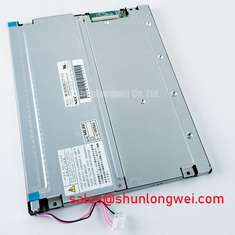
For a host assembly documented as using a CCFL inverter, distinguish a failed strike from protective shutdown by observing the inverter enable signal and lamp response together. As a Design Consideration, a brief flash followed by darkness can involve the lamp, its connections, the inverter or its feedback circuit. Establish the fitted backlight configuration from the assembly documentation before applying this diagnostic path to an LM64K10 installation.
Use appropriately rated measurement equipment when investigating an inverter output, accounting for probe loading and the measurement method specified by the equipment supplier. Strike behaviour and sustained lamp operation are separate conditions; a waveform captured during ignition cannot establish correct running current. Lamp voltage, current and protection thresholds must come from the matched lamp and inverter specifications rather than generic CCFL figures.
Inspect cable routing, connector seating and nearby contamination before considering threshold adjustment. As an Engineering Recommendation, preserve the original protection function and investigate why it operates before changing its setting. Required electrical clearances depend on the complete assembly, insulation system and applicable equipment requirements. Changing a trip threshold to conceal an intermittent connection leaves the underlying fault unresolved.
Assess illumination uniformity after the equipment reaches a repeatable thermal condition. Compare dim regions and background tint with the same optical path and instrument settings, separating panel modulation from illumination effects. For broader enclosure, cable routing and maintenance considerations, Industrial Display & HMI Solutions provides supporting integration context without replacing the matched backlight specifications.
Elastomeric Zebra Strip Connector Compression & Heat-Seal (HSC) Interconnect Integrity
Inspect accessible cable exits, connector locks and bezel seating before investigating bonded internal interconnects. As a Design Consideration, a missing row or column can originate in host data, a connector, a driver path or an internal connection; its shape alone does not identify the failed element. Record whether the defect changes after an approved external cable reseat, then repeat the original test patterns.
💡 Bench Tip: With power isolated and ESD precautions in place, seat the cable squarely and close its lock evenly before restoring power.
Where the assembly documentation identifies an elastomeric contact or heat seal connection, preserve its specified alignment and retention arrangement. Compression and bonding requirements are construction dependent; applying an arbitrary bezel pressure or reheating a bond can introduce additional damage. Avoid pressing the active viewing area to obtain a temporary image, since that observation cannot establish a durable repair.
As an Engineering Recommendation, support the external cable so enclosure closure does not pull it sideways or concentrate repeated bending at its termination. After reassembly, repeat uniform fields, alternating patterns and text screens with the bezel fully secured. Record connector seating, visible line continuity and any change after normal enclosure handling so the acceptance record reflects the installed mechanical condition.