Content last revised on September 10, 2026
Preventing Frame Lag & Image Smearing in Cryogenic Storage & Outdoor Industrial Facilities
When a display is removed from a cold enclosure, allow the panel and its connector area to reach a stable service temperature before applying power. Temperature changes can affect liquid-crystal response, cable flexibility, seal interfaces, and the behavior of the host display controller. A slow image transition, partial smear, or delayed grey-level change should be assessed against a known-good signal source rather than assigned to the panel immediately.
The published product context confirms the industrial-grade LCD/HMI panel category, but it does not confirm a guaranteed operating-temperature range for this exact model. Engineers evaluating the unit for outdoor cabinets, cold-storage monitoring, or substation control rooms should obtain the original manufacturer datasheet and compare its operating and storage limits with the enclosure profile. Heater control, condensation management, sunlight exposure, and airflow can be system-level factors that influence image stability.
Backlight control also requires documentation matching. Do not assume that this model accepts a particular PWM frequency, dimming polarity, duty-cycle range, CCFL interface, or LED constant-current driver. The system integrator should verify the required backlight method from the original panel documentation. If the replacement is connected to a different backlight architecture, the host controller may require an interface adapter or a separate driver evaluation.
For troubleshooting, display a fixed text pattern, a moving grayscale test image, and a full-screen field while recording the panel temperature and supply behavior. Compare the result with the original unit or a known-good assembly under the same controller settings. If the image appears stable at room temperature but changes during a cold transition, examine the enclosure temperature profile, connector strain, controller timing, and backlight regulation together. The available factory information does not establish a specific GTG response value, contrast ratio, or low-temperature performance figure for LTM150XS-T01.
Logic Supply Voltage Sequencing to Eliminate Driver IC Latch-Up Risks
Power sequencing must be checked at the panel connector with an oscilloscope, not inferred from the host equipment label. The supplied factory specification context does not identify whether the logic rail for this model is 3.3 V or 5.0 V, and it does not publish confirmed rise-time limits, reset timing, or absolute maximum ratings. Do not select between these voltage classes from a generic LCD assumption; verify the required supply voltage from the original panel documentation.
The same rule applies to the video interface. The available record does not confirm LVDS, TTL, JEIDA, VESA, single-channel, dual-channel, connector pin assignment, or pixel-clock timing for this exact display module. Before moving the panel into a high-voltage substation protection or SCADA dispatch console, capture the signal from the original system and compare its data mapping with the replacement documentation. A wrong mapping can produce swapped colors, split-screen imagery, unstable synchronization, or a blank display even when the power rail appears correct.
| Verification item | Required engineering action |
| Logic supply | Confirm nominal voltage, tolerance, sequencing, and absolute maximum limits from the original panel documentation. |
| Video interface | Confirm connector pinout, channel count, data mapping, clock polarity, and timing compatibility. |
| Differential routing | Preserve the host designer’s controlled-impedance and pair-matching strategy, then validate signal quality at the panel connector. |
| Ground reference | Check shield, signal return, chassis bonding, and cable routing for unwanted common-mode disturbance. |
💡 Pro Tip: Keep each differential pair continuous and closely matched through the complete cable path, then verify eye quality and clock stability at the receiving connector instead of relying only on continuity testing.
In a factory or substation cabinet, image corruption can also be affected by contact resistance, cable shielding, converter noise, grounding, or a controller that is outside its original timing configuration. If the panel shows intermittent artifacts, compare the known-good signal path with the suspect path using the same source pattern. A logic analyzer or oscilloscope can help separate a panel-interface problem from a controller, cable, or power-integrity issue.
High-Voltage Striking Potential & Secondary Coil Insulation Testing
The available factory context does not confirm whether LTM150XS-T01 uses a CCFL backlight, an LED backlight, or a particular high-voltage inverter arrangement. The system integrator should verify the backlight architecture and test requirements from the original documentation before applying any secondary-side measurement or replacement driver. A CCFL inverter and an LED constant-current driver are not interchangeable interfaces, even when the display opening and connector location appear similar.
For a panel removed from a high-voltage substation protection or SCADA console, begin with a visual inspection of the backlight connector, cable insulation, inverter area, and chassis clearances. With power isolated, check for contamination, carbon tracking, crushed insulation, and loose mounting hardware. Any insulation-resistance or dielectric withstand procedure must be selected according to the equipment manufacturer’s service instructions and the applicable safety procedure. The display module’s available specification record does not provide a dielectric rating, striking-voltage value, insulation class, or certified high-voltage test limit.
Do not describe a replacement display as having a guaranteed operating life, half-life, MTBF, or sunlight contrast performance unless those figures are present in an authoritative datasheet or test report for the exact part revision. Ambient light, optical bonding, front-surface treatment, backlight aging, controller brightness settings, and enclosure glass can all influence readability. Engineers evaluating direct sunlight exposure should measure the complete installed assembly under the intended viewing angle and ambient-light condition.
For installations near switching equipment, inspect the complete signal and power topology. Minimize coupling between inverter or backlight wiring and the video cable, maintain suitable separation according to the equipment design, and verify the display image during switching events. The component itself cannot be represented as independently passing a complete system EMC certification. Where sensitive control electronics are exposed to transient radiation or high-energy switching environments, the system team may consult the discussion of Single Event Effect and Cosmic Ray Latchup Mitigation as general industry background, while applying the actual equipment-level qualification method.
Chassis Fastener Torque Sizing to Eliminate Optical Mura Defects
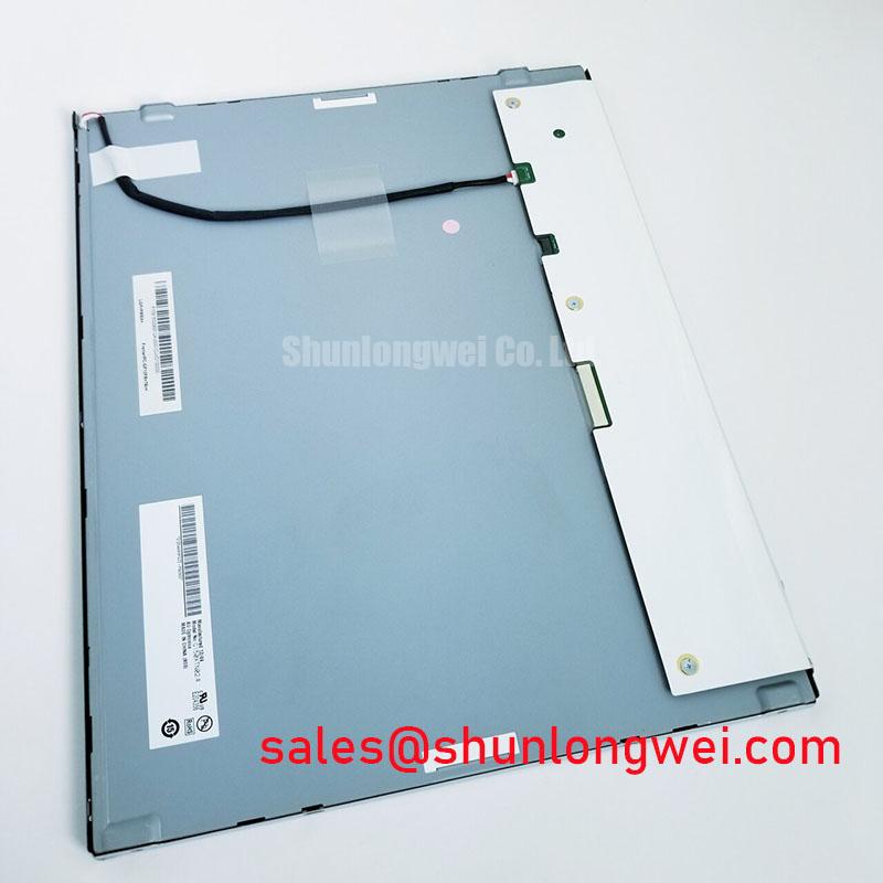
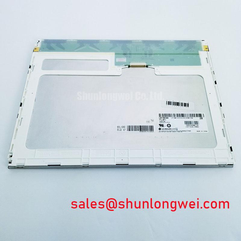
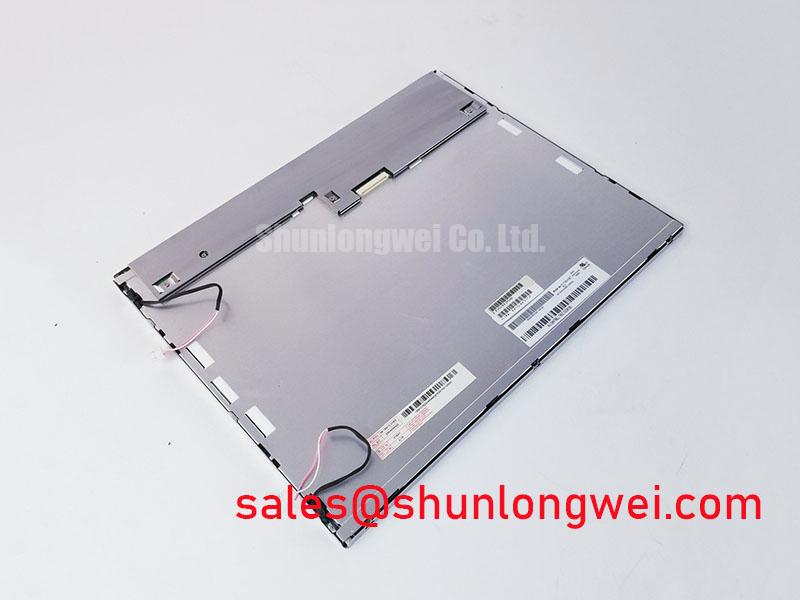
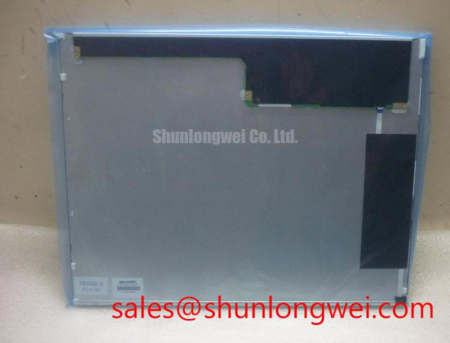
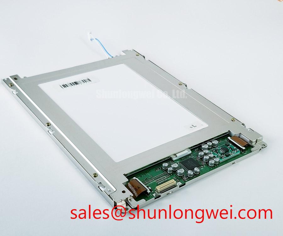
Mechanical compatibility should be checked before the panel is placed behind the SCADA console bezel. The available factory record identifies the enclosure as a TFT-LCD Display Module, but it does not include the outer bezel envelope, active-area dimensions, mounting-hole pattern, connector offset, panel thickness, or approved fastener torque. Measure the original assembly and compare every mounting datum with the replacement documentation. A visually similar screen can still fail because of bezel interference, cable bend stress, or a connector that does not align with the chassis opening.
During a trial fit, support the module evenly and confirm that the bezel does not press against the viewing area. Tighten fasteners progressively in a cross-pattern only when the chassis drawing or service manual specifies the sequence. Fastener torque is a design consideration governed by the thread size, bracket material, washer arrangement, panel frame, and enclosure stiffness; it should not be treated as an official parameter of LTM150XS-T01 without a manufacturer instruction.
After installation, display a uniform white field, a mid-gray field, and a dark field. Observe the panel from the intended viewing position while checking for localized brightness variation, edge pressure, frame distortion, and changes caused by tightening or loosening the bezel. Optical mura can arise from mechanical stress, contamination, diffuser condition, backlight uniformity, viewing angle, or camera exposure, so the evaluation should compare the complete installed assembly with the original unit.
Route the display cable without forcing it against a sharp chassis edge or the rear of the panel. Confirm that the connector locking method is engaged and that service access does not transmit pulling force into the glass or circuit board. If the application includes frequent door movement or vibration, the cable support and strain relief should be validated as part of the enclosure design rather than assumed from the display-module label.
For broader enclosure, HMI integration, thermal, and field-service considerations, engineers can use the Industrial Display & HMI Solutions reference alongside the original equipment documentation. Any final acceptance decision should be based on confirmed electrical, optical, thermal, and mechanical data for the exact panel revision and the target control console.