Content last revised on September 10, 2026
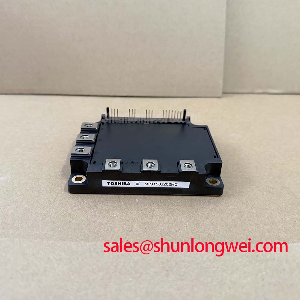
Toshiba MIG150J202H Intelligent Power Module: High-Efficiency Power Control for Industrial Motor Drives
Toshiba's MIG150J202H integrates a three-phase inverter, dynamic brake, and comprehensive protection circuitry in a single package to simplify high-performance motor drive designs. With peak ratings of 600V and 150A, and a low inverter IGBT thermal resistance Rth(j-c) of 0.390°C/W, this module slashes gate-drive complexity and prevents thermal runaway. For variable frequency drive systems requiring built-in dynamic braking, it directly resolves design risks with an integrated 118°C over-temperature fault trigger.
Application Scenarios & Value
Achieving System-Level Benefits in High-Frequency Power Conversion
For 400V inverter designs demanding integrated dynamic braking, this 600V, 150A module provides the optimal balance of speed and protection.
Engineers often face the daunting challenge of managing high-frequency switching losses and massive peak currents during motor startup in heavy conveyor systems. When a heavily loaded conveyor belt starts up, the motor draws a high surge current that can easily push discrete switches past their dynamic limits. Selecting a pre-packaged IPM (Intelligent Power Module) avoids these issues. The MIG150J202H mitigates gate-loop parasitic inductance and controls over-current spikes through its integrated over-current protection trip level of 190A to 300A.
By bypassing the complexities of discrete gate layout design, this module cuts design iteration cycles. While this model is highly effective for medium-power applications, smaller designs can use the related MIG50Q201H with a 50A rating. For larger systems, the related MIG200Q101H supports up to 200A. Evaluators can find further guidance on IPM vs discrete IGBT design options to weigh performance tradeoffs in industrial topologies.
Technical & Design Deep Dive
Analyzing Silicon Integration and Thermal Safeguards
At the silicon level, the MIG150J202H showcases high-speed N-channel IGBT technology paired with fast recovery diodes. The module limits collector-emitter saturation voltage Vsub>CE(sat) to a maximum of 2.8V at 150A. This saturation voltage behaves much like the pressure drop across a fluid control valve; a smaller drop ensures minimal power is converted to waste heat, optimizing system efficiency.
Furthermore, the junction-to-case thermal resistance Rth(j-c) is specified at a low 0.390°C/W for the inverter IGBT. This thermal resistance functions like a wide highway for heat dissipation, allowing heat to escape quickly to the heatsink. Combined with a maximum turn-off time toff of 3.0 μs, switching losses are kept minimal. This rapid transit ensures the module stays safely within its transient SOA (Safe Operating Area). Engineers interested in thermal calculations can review guides on selecting an IGBT module to ensure proper heatsink calculation. Additional resources on preventing IGBT gate and thermal failures can assist in avoiding common field destruction modes.
Key Parameter Overview
Specs Highlighted for Precision Power System Design
| Stage / Stage Parameter | Symbol | Rating / Condition | Key Metric Highlight |
|---|---|---|---|
| Collector-Emitter Voltage | VCES | 600 V | Inverter Stage Max |
| Collector Current (DC) | IC | 150 A | Inverter Stage Max |
| Collector Power Dissipation (Tc=25°C) | PC | 320 W | High Thermal Budget |
| Collector-Emitter Saturation Voltage | VCE(sat) | 2.8 V (Max) @ 150A | Low Saturation Loss |
| Brake Stage Collector Current | IC(Brake) | 50 A | Integrated Brake Stage |
| Switching Turn-Off Time | toff | 3.0 μs (Max) | Fast Commutation |
| Over-Temperature Protection Trip | OT | 118 °C (Typical) | Integrated Sensor Protection |
| Junction-to-Case Thermal Resistance | Rth(j-c) | 0.390 °C/W (Max) | Efficient Heat Dissipation |
Download the MIG150J202H datasheet for detailed specifications and performance curves.
FAQ
Technical Solutions for High-Power Module Integration
How does the built-in under-voltage (UV) protection safeguard the MIG150J202H during operations?
The control stage continuously monitors the supply voltage. If the control supply falls below 11.0V, the protection system activates a fault output and safely shuts down the gate signals, preventing the IGBTs from operating in their resistive linear region.
What is the typical fault output pulse width (tFO) when a protection event occurs?
Under over-current, under-voltage, or over-temperature events, the fault output pin goes low for a pulse width of 2ms (typical) to ensure that the system microcontroller can shut down the main power stage before catastrophic damage occurs.
What is the primary benefit of the MIG150J202H's integrated gate drive?
What is the primary benefit of the MIG150J202H's integrated gate drive? It eliminates external driving circuit design complexities.
How does the over-temperature protection function reset?
How does the over-temperature protection function reset? It resets automatically when the case temperature drops below 98°C.
As industries demand greater motor drive compactness and enhanced reliability under harsh operating environments, choosing integrated power solutions represents a strategic path forward. By combining robust silicon performance with onboard logic, engineers can achieve strict thermal compliance and compact footprints, paving the way for next-generation industrial automation.