Content last revised on September 29, 2026
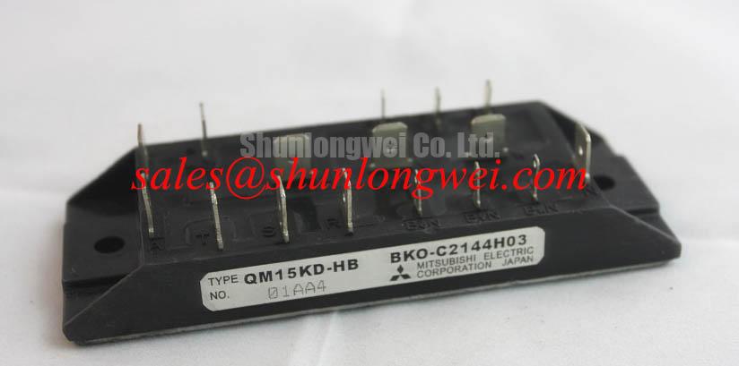
QM15TB-H Mitsubishi Electric 600V 15A Isolated Darlington Module
Begin incoming inspection by confirming the marking QM15TB-H, checking the package for cracks or deformation, and verifying the specified ratings of 600.0 V and 15.0 A against the replacement record. The manufacturer is Mitsubishi Electric, and the stated package type is an Isolated Darlington Module. These are the available official specification values for this product page; base drive, switching, thermal, isolation test, and short circuit capability should be confirmed from the applicable Mitsubishi Electric documentation before circuit approval.
| Parameter | Official specification | Integration meaning |
|---|---|---|
| Model | QM15TB-H | Confirm the complete suffix before installation |
| Manufacturer | Mitsubishi Electric | Use the original device documentation for terminal identification |
| Rated voltage | 600.0 V | Do not treat this value as a complete transient design limit |
| Rated current | 15.0 A | Actual current capability depends on operating conditions and thermal design |
| Package | Isolated Darlington Module | Check mounting, isolation, terminal polarity, and mechanical fit |
A cold state bench check should be performed with the module disconnected from the converter and protected against electrostatic discharge. Use the original circuit drawing to identify collector, emitter, base, and any auxiliary terminals because a Darlington power module should not be treated as a generic IGBT or MOSFET pinout. A diode range measurement can help compare the forward junction response with a known good unit, but a multimeter reading is only a screening observation. It does not establish rated blocking voltage, leakage under operating voltage, dynamic switching performance, or insulation withstand.
💡 Bench Tip: Use an ESD controlled bench and record the cold measurement conditions before comparing terminal readings with a known good QM15TB-H.
QM15TB-H Operational Boundaries: Evaluating Hard Switching Transients and Current Limits
The 600.0 V voltage rating defines an important product boundary, but it does not by itself define the allowable overshoot during hard switching. Wiring inductance, load current, commutation behavior, snubber arrangement, diode recovery, and DC link impedance can all affect the voltage appearing at the module terminals. When evaluating the QM15TB-H in a commercial string inverter or micro grid energy storage power stage, designers should measure the switching waveform directly at the module terminals and compare the observed peak with the applicable device documentation and system safety margin.
The available product data does not establish an internal type I or type II short circuit protection function, a short circuit safe operating area, or a guaranteed detection time below 10 microseconds. These features must not be assumed from the Darlington package description. If the converter requires rapid short circuit detection, the protection architecture should be defined at system level using an appropriate current sensor, desaturation or overcurrent method where applicable, base drive interlock, and a controlled shutdown path. The selected timing must be validated with the actual load, wiring, driver propagation delay, and measurement setup.
A two stage soft turn off sequence can be considered when the system has enough sensing and drive control to distinguish a genuine overcurrent event from switching noise. The first action limits the immediate drive energy, while the subsequent turn off controls the current transition and helps the designer evaluate inductive voltage rise. This is an Engineering Recommendation, not an official QM15TB-H function. Any turn off profile should be verified on an isolated test fixture with a properly rated differential voltage probe and current probe.
For troubleshooting, first compare the voltage waveform at the module terminals with the controller command and the current waveform. A high voltage spike that appears only when the load cable is connected may indicate a change in parasitic inductance or transmission line behavior rather than a static module fault. Long motor or converter cables can produce reflected wave effects, and the resulting peak may be higher than the local switching node waveform suggests. Designers should minimize the high current commutation loop, keep the base drive return path controlled, and select any snubber or filter only after measuring the actual ringing frequency and peak amplitude.
Protection coordination should also include the freewheel path. Reverse recovery behavior from an external diode can increase switching stress and electromagnetic emission. The diode softness factor S is not provided as an official QM15TB-H parameter, so it should not be assigned a value for this module. If a replacement diode or complementary power stage is being evaluated, measure reverse recovery current and voltage together with the module waveform. The related QM100HY-2H can be reviewed as a separate power stage reference, but compatibility must be established from the complete circuit and terminal data rather than by product naming alone.
QM15TB-H Circuit Protection and Reliability: Heatsink Contact Pressure and Switching Coordination
The official information supplied for this page does not specify thermal resistance, junction temperature, case temperature, baseplate flatness, isolation withstand voltage, or mounting torque for the QM15TB-H. Those values are essential before setting a heatsink design. The installer should obtain the original mechanical and thermal data, then verify the heatsink surface, interface material, mounting hardware, and pressure distribution as a complete assembly.
As a general Design Consideration, the thermal interface layer should be continuous and free from visible voids, contamination, and excessive material at the package edge. A nominal interface thickness such as 50 to 100 micrometres must not be treated as an official QM15TB-H requirement unless it is stated in the applicable mounting documentation. Baseplate curvature and heatsink flatness should be checked using the manufacturer’s permitted method. If the package has more than one mounting point, tighten the fasteners in a cross pattern and follow the documented sequence and torque rather than applying pressure by feel.
⚡ Safety Interlock Note: Disconnect the DC link and verify the stored energy has fallen to a safe level before removing terminals or changing the module.
Base drive coordination deserves the same care as mechanical installation. A Darlington module requires the original electrical interface to be confirmed before a driver is selected. The system integrator should verify required drive voltage, drive current, turn on and turn off behavior, and any required bias from the original Mitsubishi Electric documentation. Do not substitute IGBT gate drive assumptions for a Darlington base drive without checking the electrical characteristics.
Dead time is a system determined parameter. Too little dead time in a complementary switching leg can create cross conduction, while excessive dead time can increase freewheel conduction and distort the intended power waveform. The correct buffer depends on device storage behavior, driver delay matching, temperature, load current, and the external diode. Designers should measure both complementary drive signals at the module terminals and confirm that the interlock remains effective during power up, shutdown, fault recovery, and controller reset.
For a repair assessment, inspect the driver supply, command waveform, return connection, and current feedback before condemning the power module. A missing drive pulse, abnormal return impedance, or protection circuit that latches prematurely can produce symptoms resembling a damaged semiconductor. Compare the suspected unit with a known good signal path under controlled low energy conditions before applying the full DC link.
Reliability Considerations: Atmospheric Neutron Radiation Impact and QM15TB-H Guidelines
Atmospheric neutron effects and single event burnout are high risk reliability subjects, but no neutron cross section, FIT rate, SEB limit, altitude derating curve, or validated failure model is provided for the QM15TB-H in the supplied product data. It would therefore be inappropriate to calculate a device specific FIT value or claim a defined failure probability above a particular altitude. Operation above 2000 metres may change cooling performance and environmental exposure, yet the required derating remains dependent on the device data, enclosure, airflow, DC bus, switching condition, and site profile.
For an inverter or energy storage system installed at elevation, the engineering review should separate three questions. First, can the cooling path maintain the permitted semiconductor temperature under the local air density and enclosure conditions? Second, does the insulation system retain the required clearance and creepage performance for the actual environment? Third, is the DC bus and switching waveform within the documented device boundary after all transient effects are included? These are Design Considerations, not confirmed QM15TB-H ratings.
SEB risk analysis requires authoritative device data and a defined mission profile. The calculation should use the manufacturer’s validated voltage and radiation information where available, rather than applying a generic cosmic ray model to a product with an unknown die structure. If the equipment owner requires radiation reliability evidence, request the applicable Mitsubishi Electric qualification information or conduct a documented evaluation using representative devices, bus voltage, switching stress, temperature, and environmental conditions.
Field troubleshooting should begin with non destructive evidence. Record the DC link voltage, switching frequency, current waveform, temperature history, fault timing, and the physical location of the failed device. Inspect the base drive path, commutation loop, snubber components, and freewheel diode before attributing the event to radiation. A repeated failure after high voltage operation can also result from overshoot, inadequate cooling, contamination, or an incorrect drive sequence. Without laboratory failure analysis, the initiating mechanism should remain classified as unconfirmed.
Current measurement architecture can affect how quickly a protection system reacts to abnormal current. Designers may evaluate Hall effect sensing or magnetoresistive sensing according to bandwidth, isolation, offset, temperature drift, and placement. Background references include Hall Effect Sensors for Industrial Current Measurement and Giant Magnetoresistance Sensing Principles. These references describe sensing principles; they do not certify the QM15TB-H or a complete inverter for EMC or safety compliance.
QM15TB-H Operational Boundaries: Evaluating PCB Drive Loop Layout Symmetry
The final layout review should begin with the actual terminal arrangement of the QM15TB-H from the original drawing. The supplied product data identifies an isolated Darlington module but does not provide a verified auxiliary emitter, Kelvin emitter, base terminal map, or internal interconnection diagram. Do not create a Kelvin return by assumption. Where the documented package provides separate low current control and high current return paths, keep the control return physically separate from the main power current path and connect them according to the manufacturer’s recommended topology.
Parasitic inductance in the power loop can create an inductive voltage component during rapid current change. The practical objective is to reduce the loop area, keep forward and return conductors close together, and prevent the high current path from sharing impedance with the control reference. The suitable geometry is determined by the board, busbar, module terminals, insulation system, and measured switching waveform. The system engineer should verify peak voltage and control stability with the real enclosure and cable arrangement.
Base drive loop symmetry should be assessed by measuring the drive signal at the module terminals rather than at the driver output alone. Differences in conductor length, connector contact resistance, return routing, and common impedance can alter the effective drive waveform. If oscillation or repeated false triggering is observed, compare the control reference, power return, and switching node simultaneously. A probe ground lead can introduce its own ringing, so use an appropriately rated differential probe; use a ground spring only where an earth-referenced measurement is safe.
When the module is used near a resonant converter, switching behavior should be reviewed alongside the complete tank, rectifier, bus capacitor, and load network. The technical guide Resonant Topologies in Home Appliances provides broader topology context, while the related QM200HA-HK may be examined as a separate Mitsubishi Electric reference for comparison. Neither link establishes a direct replacement relationship for QM15TB-H.
Before approving a repaired commercial string inverter or micro grid energy storage assembly, repeat the cold static checks, confirm terminal polarity, verify the control waveform, inspect the isolation barriers, and perform a controlled low energy switching test. The 600.0 V and 15.0 A official ratings identify the basic product class, while the final operating boundary remains dependent on the documented application conditions and measured system behavior.