
Content last revised on October 29, 2026
QM15KD-HB Operational Boundaries: Driver Readiness and Start-Up Inrush
Isolate the DC link, verify that stored energy has discharged, and disconnect the driver before checking the QM15KD-HB collector, emitter, and base connections against the equipment schematic. Compare cold resistance readings with the corresponding disconnected power stage rather than assigning a universal pass voltage to a meter reading. Parallel circuitry can obscure a damaged junction or make a serviceable device appear shorted.
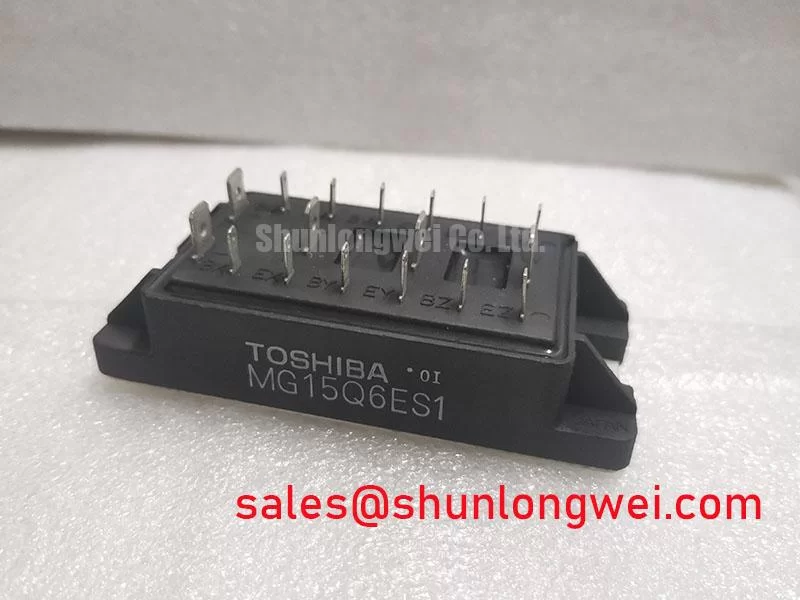
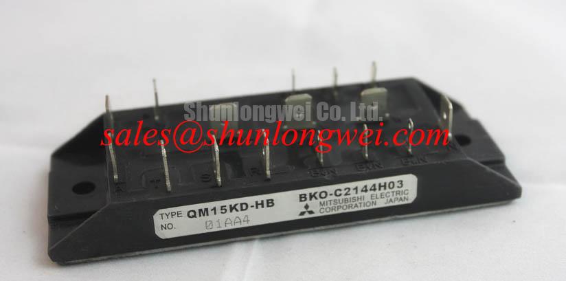
The Mitsubishi Electric QM15KD-HB is a power transistor / Darlington module, not an IGBT. That distinction matters immediately during repair: its drive interface requires base-current control, so IGBT gate-bias instructions cannot be transferred directly. The QM15KD-HB product page provides the model reference for matching procurement documentation to the equipment bill of materials.
Check whether the auxiliary driver supply reaches a stable operating state before the controller permits DC-link energization or switching commands. Design Consideration: the relevant checks are driver readiness, base-current delivery, turn-off current extraction, and the response to auxiliary-supply collapse. A negative gate-bias prescription belongs to a different device interface; it is not an established QM15KD-HB operating requirement.
The supplied Official Specification values are collector-emitter voltage Vcex: 600 V, DC collector current Ic: 15 A, collector dissipation Pc: 100 W, collector-emitter saturation voltage Vce(sat): 2.0 V, and isolation voltage Viso: 2500 V. These values must be interpreted under their respective datasheet conditions, not as universal operating allowances. Preserve the Vcex designation when comparing documentation: differently defined blocking ratings are not automatically interchangeable. The saturation-voltage test conditions and thermal conditions governing dissipation also belong in the service assessment.
Engineering Recommendation: observe the auxiliary supply, driver-enable signal, and base-emitter waveform during the equipment’s approved commissioning sequence. Look for incomplete turn-off, supply droop, or an enable signal that arrives before the driver is ready. Where the controller provides undervoltage lockout, verify its actual inhibit behavior rather than assuming the presence of a protection circuit guarantees correct sequencing.
DC-link charging inrush is principally a system-level rectifier and precharge issue. Inspect the charging path and bypass sequencing separately from the transistor driver. A startup trip can involve either subsystem, so correlate the charging waveform with the switching-enable event before attributing the fault to the module.
When a repair assessment includes a CM200DY-12NFH elsewhere in the power-stage documentation, treat it as a separate device requiring its own interface review. It is not evidence that the QM15KD-HB accepts the same driver, and its presence does not establish a rectifier function. For manufacturer technology references, use Mitsubishi Electric Global Semiconductor Device Technologies alongside the equipment schematic.
Assembly Integrity & Layout Architecture: Thermal Capacitance and Heatsink Performance for QM15KD-HB
Inspect the mating surfaces and the previous thermal-interface contact pattern before refitting the module. Design Consideration: uneven contact, contamination, or mechanical distortion can increase the temperature difference between the module case and heatsink. Select interface material and its applied thickness to suit the approved assembly specification, surface condition, and mounting pressure rather than imposing a generic thickness.
The 100 W collector-dissipation specification is not an instruction to operate continuously at that loss. For pulsed loading, an engineering thermal calculation should combine the actual power-loss waveform with the manufacturer’s transient junction-to-case thermal response. A fitted thermal network is useful only when its coefficients represent the device and its defined boundary conditions; heatsink thermal mass alone does not establish peak junction temperature.
Engineering Recommendation: assess repeated loading with the case temperature measured at the specified location, allowing for heat retained between pulses. Use the documented junction-temperature limit and thermal model to judge the resulting margin. An apparently cool heatsink during a brief overload does not independently demonstrate acceptable junction temperature.
For replacement planning, the comparison below separates the supplied QM15KD-HB specifications from another Mitsubishi device family without implying interchangeability.
| Selection checkpoint | QM15KD-HB | CM150DY-12NFA comparison requirement |
|---|---|---|
| Device interface | Power transistor / Darlington; base-current drive | Review IGBT gate-drive requirements separately |
| Collector-emitter rating | 600 V Vcex — Official Specification; subject to datasheet conditions | Consult datasheet for rating definition and conditions |
| DC collector current | 15 A — Official Specification; subject to datasheet conditions | Consult datasheet for current and temperature conditions |
| Mechanical integration | Match terminal arrangement and mounting drawing | Compare outline, connections, and mounting requirements |
The CM150DY-12NFA is a comparison reference, not a declared drop-in substitute. For a compact industrial inverter or high-speed CNC spindle drive, compatibility assessment should cover control circuitry, switching behavior, protection, and mechanical fit—not just headline voltage.
Field Alert: Tighten the mounting hardware in the approved sequence and to the specified assembly torque, rather than borrowing a torque value from another module.
Field Diagnostics & Commissioning: Reflected-Wave Voltage Doubling in QM15KD-HB Applications
Measure motor-terminal voltage separately from the voltage across the switching device when investigating cable-related overshoot. Design Consideration: an impedance mismatch between a motor cable and its termination can produce reflected voltage waves; the idealized doubling case is not a guaranteed QM15KD-HB waveform or an additional device rating.
Use appropriately rated differential measurement equipment and a connection arrangement suitable for the switching environment. Compare the drive-end and motor-end waveforms under the same operating condition. Reflections associated with cable propagation and overshoot associated with the local commutation loop can require different remedies, even when both appear as narrow peaks on an oscilloscope.
Engineering Recommendation: evaluate an output reactor or dv/dt filter using the drive’s switching behavior, cable characteristics, motor insulation requirements, and permitted voltage drop. Filter selection remains a system calculation; a module’s current rating alone does not determine choke inductance or damping. Keep local commutation connections compact, preserve the equipment’s required clearances, and repeat waveform checks after any layout or cable change.
The 2500 V isolation voltage is an Official Specification, not a continuous working-voltage allowance or permission to repeat dielectric testing without an approved procedure. The distinction between material dielectric strength and an assembly test is explained in Dielectric Strength and High-Voltage Breakdown Testing. Use the prescribed test conditions when assessing the module-to-base insulation boundary.
For broader switching-loss and drive-efficiency context, Unlocking Efficiency in Industrial Drives discusses newer IGBT technology; its device-specific conclusions should not be transferred to this Darlington module. During recommissioning, record the actual base-drive waveform, collector-emitter peak voltage, case-temperature trend, and protection response against the equipment’s acceptance criteria before restoring normal loading.