Content last revised on October 8, 2026
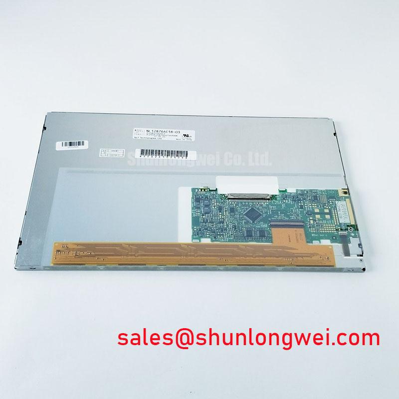
NL12876AC18-03D Identification and Incoming Inspection
Display a full red test image on the NL12876AC18-03D before fitting it into a console, then repeat with green and blue while checking for fixed vertical lines, dark pixels, and uneven illumination. Record the results against the incoming inspection criteria before connecting the panel to the equipment harness. The verified product identity is an NEC industrial grade LCD/HMI panel in a TFT-LCD display module assembly (Official Factory Specification). The available factory information does not establish its viewing angle, resolution, interface pinout, supply voltage, or backlight type; those details require the applicable panel documentation before electrical integration.
Wide Viewing Angles and Glare Checks for Multi-Angle Consoles
A marine radar or navigation bridge console can be read from several standing and seated positions. For the NL12876AC18-03D, do not treat a wide viewing cone or a particular liquid-crystal mode as a confirmed specification without the corresponding NEC optical data. Instead, place the powered panel at its intended installation angle and inspect the same chart from each operator position. Pay particular attention to fine chart labels, dim symbols, and gray areas: loss of contrast can matter even when bright primary colors still look acceptable.
TN, IPS, and MVA are distinct display technologies, and their off-axis grayscale behavior should not be inferred from the TFT-LCD description alone. A claim of symmetric viewing angles needs an optical specification that defines the contrast criterion and measurement directions. As a Design Consideration, evaluate viewing performance with the actual bezel and cover window installed. Their reflections and mounting angle can change what an operator sees, regardless of a bare panel’s laboratory viewing-angle result.
Bridge lighting adds another variable. A surface that appears readable indoors may show strong reflections near a window or under directed task lighting. Check the face of the installed display for reflections at the positions where operators normally read it. Do not assume an anti-glare etch or coating is present on this model without confirmation. If an external cover lens is part of the console, assess that lens and the panel together; a favorable finish on one surface does not eliminate reflections from the other.
During replacement assessment, compare the original module’s mechanical drawing, active display area, mounting points, interface, power requirements, and optical behavior before considering another part. The NL8048AC19-13KD is a separate model for cross-model evaluation, not a verified drop-in replacement for the NL12876AC18-03D. Matching an apparent screen size or a catalog description would not establish connector or timing compatibility.
Single Vertical Hairline Defects and Column-Driver Fault Localization
Run a primary-color inspection in three passes: fill the screen with red, then green, then blue. Examine the full active area at a consistent viewing distance and note whether a suspected line remains in the same column, changes color, or disappears between patterns. Follow with a dark image to inspect bright leakage and a light image to reveal darker regions. Photograph each finding with the displayed pattern identified; this gives a repair engineer a more useful record than a photograph of an operating application screen.
A persistent hairline can be consistent with a signal-path, column-drive, connection, or panel defect, but appearance alone does not identify which one. Inspect the connector seating and the source video path before assigning the fault to the display assembly. Where access and test equipment permit, compare the incoming signals with those of a known-good installation using the correct interface documentation. Avoid pressing on a suspected bond area as a diagnostic shortcut: a temporary image change does not establish a durable repair.
A flashlight examination helps distinguish image-generation problems from illumination problems. With the module displaying a known pattern, shine a flashlight obliquely across the face and observe the affected region from an angle. A dark area that still contains a discernible image may direct attention toward the illumination path; a sharply defined, pattern-dependent vertical line calls for further signal and panel inspection. This is a screening technique, not a definitive test of a backlight or driver connection.
💡 Bench Tip: Wear an ESD wrist strap and support the flexible cable while opening its connector latch; pulling the cable or making a tight fold can add a second fault to the inspection.
For a navigation console exposed to vibration, inspect cable routing after the panel is seated, not only while it lies flat on the bench. A cable that clears the bezel during assembly can be pinched when the cover is secured. As a Design Consideration, leave routing and strain relief to the equipment’s mechanical requirements, and check that the connector remains fully latched after the enclosure is closed. Further context on display integration and fault isolation is available in Industrial Display & HMI Solutions.
Gray-to-Gray Response During Cold-Start Power-Up
At a cold start, watch a moving cursor or a controlled grayscale transition before deciding that a delayed image indicates an interface fault. Liquid-crystal response can slow as temperature falls, while a weak video connection or an unstable source can produce different artifacts that deserve separate investigation. Record the ambient and panel conditions when the symptom occurs, then repeat the same pattern after the assembly has reached a stable operating condition. Compare like with like: changing the graphics source or test image between runs makes the result harder to interpret.
No operating-temperature range or gray-to-gray response-time limit for the NL12876AC18-03D is established by the supplied factory information. Temperature endpoints sometimes quoted for industrial panels must not be transferred to this model. If a bridge-console design uses a heater, its control, placement, and permissible operating conditions need to be checked against the equipment design and the applicable panel specification. Do not use a heater to justify operating a panel outside its documented limits.
Cold-to-warm transitions also warrant a mechanical inspection. Check the bezel for uneven contact, the module for distortion, and the cable for tension as the assembly changes temperature. The perimeter seal and internal bonds should not be assigned an assumed thermal-cycle rating without manufacturer data. As a Design Consideration, the enclosure should support the module without concentrating load at one edge; the system engineer should verify the arrangement under the equipment’s expected conditions.
Long periods showing an unchanged radar or HMI layout call for a separate image-quality check. Display a neutral test pattern after the static interface has been shown and note any residual image, its location, and whether it changes with continued operation. Residual imagery is not proof of a particular internal failure mechanism. The equipment designer should assess screen-content management and operating conditions against the panel’s documented limits rather than relying on an unsupported claim that the module is immune to image retention.
Direct sunlight is another system-level test, not a specification that can be inferred from the words “industrial grade.” Evaluate legibility with the installed cover, intended brightness controls, and representative console graphics. A numerical sunlight contrast claim requires a defined measurement method and verified optical data. Without those, a side-by-side observation under controlled lighting is useful for assessment but should not be reported as an official contrast rating.
Backlight Driving, Dimming, and Interface Verification
Identify the backlight arrangement from the original panel documentation before connecting an inverter or constant-current driver. The supplied identity for the NL12876AC18-03D does not confirm whether its illumination uses a particular lamp or LED configuration. CCFL ignition requirements and WLED drive methods are not interchangeable, so neither a CCFL voltage nor an LED current should be assigned to this model by analogy with another NEC display.
If the host console dims its display, inspect the complete dimming path: host command, driver behavior, and visible output. At the lowest intended setting, look for flicker during eye movement and listen for noise from the assembled electronics. As a Design Consideration, pulse-width modulation frequency and duty-cycle behavior should be evaluated in the actual system; the panel identity alone does not establish a permitted frequency, dimming ratio, or flicker performance. Any claimed backlight service life likewise needs a model-specific manufacturer source and defined test conditions.
Keep the image interface investigation equally specific. Do not select a TTL or LVDS transmitter, map connector contacts, or set clock timing from the TFT-LCD product category. Obtain the matching connector and timing documents, confirm pin orientation on both sides of the harness, and verify the specified power sequence before applying signals. Where intermittent images appear during cold start or vibration, check connector retention and observe the relevant supply and video signals with suitable instruments. Timing margins and data hold requirements belong to the confirmed interface specification, not to a generic industrial-panel assumption.
Before returning the console to service, repeat the primary-color inspection with the module fully mounted and the enclosure closed. Compare brightness across the screen, check the previously noted defect locations, and confirm that dimming and image updates remain stable as the harness sits in its final position. Document any unresolved optical or connection issue against the equipment’s acceptance criteria rather than attributing it to the panel without isolation.