

Content last revised on October 12, 2026
Shielded FFC/FPC Flat Flexible Cable Grounding across 360-Degree Connector Shells
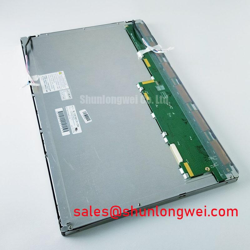
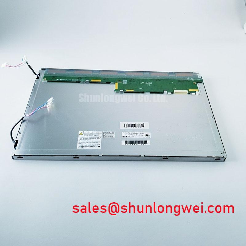
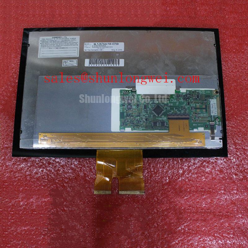
I would first compare any pixel jitter or horizontal noise bands with the switching activity of nearby drive electronics, then inspect the display cable’s shield termination without disturbing its routing. This separates an interference investigation from a controller configuration problem. For the NEC NL12876AC18-07DC, connector identification must precede electrical testing: a flat cable’s appearance does not establish its signal assignment, supply polarity or interface protocol.
Design Consideration: where the host assembly uses a shielded display interconnect, a circumferential shield connection can reduce the impedance of the enclosure bond compared with a long drain-wire connection. This is an enclosure and cable design choice, not a confirmed feature of this panel. Inspect connector seating, shell contact surfaces and continuity across the intended chassis connection. If common-mode suppression is being evaluated, compare image stability and signal quality before and after the change; an added ferrite should not conceal a damaged connector or an incorrect return path.
For an LVDS host, the compatibility check should cover differential pair assignments, clock configuration, data mapping and the receiver’s timing requirements. JEIDA and VESA mapping differences can produce incorrect colors even when synchronization appears stable. If the documented interface is TTL, use its corresponding timing and return-path requirements rather than applying LVDS rules. Establish the actual interface from the panel documentation before selecting either approach.
Pro Tip: As a Design Consideration, preserve differential pair symmetry through the cable and adapter transitions, then validate timing margin at the receiver rather than relying on trace-length matching alone.
The NL10276AC30-53D is a separate reference for a display comparison, not an established replacement. Compare documented resolution, outline dimensions, connector location and controller requirements before considering interchangeability. Backlight PWM testing belongs to the same compatibility review: select frequency and duty-cycle limits from the driver requirements, then check visible flicker, low-brightness stability and acoustic behavior throughout the intended adjustment range.
Optical Luminance Degradation Curve & CCFL-to-LED Modernization Retrofit Pathways
Measure center luminance and screen uniformity with a repeatable test image before deciding whether a dim NL12876AC18-07DC requires a backlight intervention. Keep the viewing angle, warm-up condition, brightness command and ambient illumination consistent between measurements. A darker image can involve the illumination subsystem, its power supply, the brightness control path or optical contamination; a single brightness observation does not isolate the cause.
Design Consideration: CCFL-to-LED modernization is a comparison between illumination architectures, not confirmation of this model’s installed backlight. A CCFL system requires an inverter matched to its lamp and ignition characteristics. An LED system requires regulated current matched to its light-source configuration. Neither architecture should be connected to the other’s driver merely because the mechanical connection can be adapted. A retrofit assessment should establish electrical compatibility, optical distribution and mechanical access before any modification is proposed.
For a documented LED conversion, evaluate the constant-current driver across the intended dimming range. Check whether the brightness command produces a smooth optical response, whether short pulses settle correctly, and whether the driver reports open-load or short-circuit conditions. Protection thresholds and restart behavior are driver-specific. During troubleshooting, compare fault outputs with supply and illumination behavior instead of treating a fault indication as proof that the display itself has failed.
The LQ123K1LG03 provides another display-system reference when comparing panel and illumination arrangements; it is not a backlight driver or a confirmed electrical match. Procurement comparisons should keep each panel paired with its own interface and illumination documentation. Connector compatibility alone cannot establish compatible current regulation or dimming control.
A luminance maintenance curve describes changing light output under specified conditions. MTBF describes a different reliability measure and cannot be substituted for a brightness half-life. No service-life value is assigned here to the NL12876AC18-07DC. For a maintenance decision, retain measured brightness trends and the applicable manufacturer test conditions. Evaluate glare separately: an added cover lens, protective film or surface treatment can change reflections and contrast without changing the backlight’s output.
High-Nits Edge-Lit LED Rail Thermal Dissipation & PMMA Light Guide Plate Preservation
Inspect the mounting clearances and bezel contact pattern before increasing brightness or adding a thermal spreader around the display edges. Mechanical pressure can affect image uniformity, while an obstructed thermal path can increase local temperature. For the NL12876AC18-07DC, high-luminance performance, edge-lit construction and PMMA materials are not established by the supplied product identity; they should not become assumptions in a replacement specification.
Design Consideration: if an independently documented illumination assembly places LED sources along an edge, assess the heat path from that assembly to the chassis under sustained operation. A proposed aluminum spreader needs suitable contact geometry and electrical clearance without loading the glass or deforming the frame. Determine its dimensions from measured thermal behavior and enclosure constraints, not from a generic rail size. Preserve the optical assembly’s original spacing rather than attempting to improve cooling by compressing it.
For mechanical integration, compare the mounting-hole pattern, module thickness, connector access and active-area position with the enclosure drawing. A matching bezel opening does not establish that the frame fits without stress. Designers evaluating this panel for a high-voltage substation protection terminal or SCADA dispatch console should also check viewing direction, readable contrast through the protective window and access for servicing. Any touch overlay is a separate integration item; glove and wet-touch performance belongs to the complete sensor, controller and cover-stack evaluation.
The Tianma Industrial TFT Display Solutions resource provides manufacturer-side industrial display context. Model-specific claims still require the applicable panel specification; a product-family discussion does not establish this module’s brightness, surface treatment or thermal limits.
Engineering Recommendation: evaluate moving text and grayscale transitions during a controlled cold start if low-temperature operation is required. Slower liquid-crystal response can impair readability even when an image remains synchronized. Any proposed heater should be treated as a separately validated enclosure modification, with temperature sensing and control assessed against the panel’s documented limits. Do not infer cold-start capability from successful room-temperature operation.
High-Humidity Storage Margins (60°C / 90% RH) & Delamination Prevention Protocols
Check packaging dryness, connector cleanliness and evidence of moisture exposure before energizing a stored panel. The 60°C / 90% RH condition in this section heading is an environmental assessment topic, not an official storage rating or qualification result for the NL12876AC18-07DC. Storage, powered operation and accelerated humidity testing have different acceptance conditions and should not be treated as interchangeable.
Design Consideration: allow a cold display assembly to reach a suitable dry handling condition before applying power where condensation is possible. Inspect accessible optical edges and connector areas without separating bonded layers. Haze, lifting or uneven transmission warrants comparison with a reference image and examination of the assembly; it does not establish a particular sealant failure. Cleaning agents and added adhesives should be assessed for compatibility rather than selected solely for their apparent moisture resistance.
Humidity protection also depends on the surrounding equipment. Check enclosure joints, cable entries and the protective window for paths that can admit moisture or retain it near the display. An external seal should not impose pressure on the panel frame or obstruct service access. Use the installation drawing to control gasket compression and clearance, with acceptance based on the completed enclosure rather than an assumed panel-level sealing capability.
For broader enclosure and validation considerations, Industrial Display & HMI Solutions provides supporting engineering context. Environmental qualification for this replacement remains tied to the exact panel documentation and the host equipment’s requirements.
During thermal recovery testing, compare grayscale transitions, brightness stability and connector behavior before and after the specified exposure. Where cold-response compensation is required, evaluate controller settings or a separately designed thermal-control arrangement without exceeding documented operating limits. Record the exposure conditions alongside the observed behavior so that a slow response, temporary optical change or persistent defect can be assessed without assigning an unsupported lifetime prediction.