Content last revised on October 9, 2026
Constant Luminance Output Control & L70/B50 LED Half-Life Reliability Verification
| Parameter | Official baseline |
|---|---|
| Model | NL4823BC37-05 |
| Manufacturer | NEC |
| Product category | Industrial Grade LCD/HMI Panel |
| Display technology | TFT-LCD Active Matrix Color Display Module |
| Specification status | Decoded Baseline / Standard Form Factor |
| Resolution, supply voltage, dimensions and interface mapping | Consult Datasheet |
Measure luminance across the active viewing area after the display reaches thermal equilibrium, then compare the centre and edge readings under the intended backlight drive condition. This incoming QA check helps identify uneven illumination, local thermal concentration and gradual brightness drift before the panel is installed in a railway passenger information system or cab signalling display.
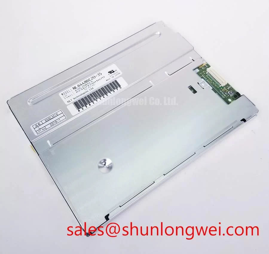
The NL4823BC37-05 is identified in the supplied baseline as an NEC TFT-LCD active matrix colour display module. The baseline does not assign a manufacturer-rated L70, B50 or backlight lifetime to this model, so those values should not be treated as product specifications. L70/B50 evaluation is a system-level reliability method for the selected backlight and driver combination, not a confirmed rating for this display unless supported by the applicable technical documentation.
As a Design Consideration, narrow aluminium heat-spreader rails may be evaluated along the display edges when enclosure testing reveals a local temperature gradient. The purpose is to distribute heat away from concentrated regions without applying mechanical pressure to the panel frame. Engineers should check the result with an infrared survey and a luminance map rather than assuming that a metal rail will improve brightness uniformity in every chassis.
For constant-current backlight systems, record the driver output behaviour during cold start, normal operation and dimming transitions. A stable current profile is useful when comparing brightness decay over an extended qualification programme. The requested 50,000-hour to 50% brightness reference is an engineering evaluation target supplied for the test plan, not an official lifetime declaration for the NL4823BC37-05.
For industrial HMI and rail display integration, optical measurements should also be compared at low ambient temperature, normal room conditions and elevated enclosure temperature. The equipment designer should determine whether warm-up compensation, brightness feedback or a controlled dimming curve is required. Reference material on TFT operating principles and selection considerations is available in The Ultimate Guide to Industrial TFT LCD Technology.
Chassis M3 Fastener Torque Sizing (0.35–0.45 N·m) to Eliminate Optical Mura Defects
Inspect the panel while displaying a uniform white field and a dark field before final chassis tightening, then repeat the inspection after the bezel is secured. A change in corner brightness, edge shadowing or local dark-field variation can indicate uneven frame loading, enclosure distortion or an installation tolerance problem.
The supplied 0.35–0.45 N·m M3 torque range is a general Design Consideration for chassis assembly evaluation, not an NEC factory specification for this display. The correct value depends on the fastener, bracket material, washer arrangement, thread engagement and bezel construction. A cross-pattern tightening sequence can help distribute loading, but the final method should be confirmed through optical inspection and mechanical fit testing.
Keep the outer bezel envelope square and avoid using fasteners to pull a misaligned chassis into position. The display should sit naturally against its support points, with the frame and mounting surfaces free from burrs, cable interference and foreign particles. Excessive compression can alter the optical appearance even when the electrical image data is correct.
When a dark-field mura pattern appears, compare the result with the panel removed from the enclosure and then with the bezel installed without final torque. This comparison separates display-originated non-uniformity from installation stress without assigning a single cause prematurely. For replacement planning, engineers may also review the similarly catalogued NL8060BC31-42, subject to a complete mechanical, optical and electrical compatibility review.
💡 Bench Tip: Protect the panel from ESD and keep the flexible cable straight and fully seated before applying the locking force.
Logic Supply Voltage Sequencing (3.3V/5.0V) to Eliminate Driver IC Latch-Up Risks
Capture the panel supply rise and interface activity together during power-up, with the oscilloscope ground connected at the display-side reference point. Confirm that the actual logic voltage, enable order and data activity match the original equipment documentation before investigating image splitting, missing sections or unstable startup.
The supplied baseline does not identify whether this specific NEC panel requires a 3.3 V or 5.0 V logic supply, nor does it confirm JEIDA or VESA mapping. These items must be treated as integration checks rather than assumptions. A system integrator should verify the original panel documentation, connector pinout and controller-board configuration before applying power.
The requested 0.5 ms to 10 ms supply rise-time window is a system-level verification criterion provided for the integration plan. It is not presented here as an official rating for the NL4823BC37-05. During testing, observe supply overshoot, enable timing and the relationship between power rails and differential data. If the image is divided, shifted or intermittently absent, compare the signal mapping and polarity against a known-good controller configuration.
Routing should maintain a controlled differential environment appropriate to the selected interface. The supplied 100-ohm differential characteristic impedance reference is a Design Consideration for the host board and cable path, not a confirmed panel specification. Connector discontinuities, excessive stubs, poor reference planes and cable strain can all affect signal quality. Designers should validate the complete path with the actual controller, cable and enclosure arrangement.
Contrast testing under direct ambient light is also useful for railway cab and passenger information applications. The requested value of greater than 500:1 at 50,000 lux should be treated as a system optical test target, not an official contrast specification for this model. Anti-glare or anti-reflective treatment must be verified on the actual supplied panel because surface treatment, viewing angle and cover glass can change the result.
For a broader display-chain assessment, the related NL192120AC25-02 may be reviewed as a separate display solution within the surrounding system topology. It should not be treated as a drop-in substitute without confirming the connector, timing, optical format and mechanical envelope.
Suppressing Acoustic Capacitor Buzz & EMI Emissions across 200 Hz to 1 kHz PWM Frequencies
Listen to the complete display assembly during brightness changes while monitoring the backlight driver waveform and enclosure vibration. Audible noise may originate from the driver, magnetic components, capacitors, mounting structure or PWM interaction, so the panel should be evaluated together with its actual power and dimming hardware.
The supplied comparison between high-voltage CCFL ignition at 1500–1650 Vrms and constant-current LED driving with 1000:1 PWM dimming describes alternative backlight architectures for system assessment. It does not confirm that the NL4823BC37-05 uses either architecture. The original equipment configuration and applicable panel documentation must establish the backlight type before replacement wiring or driver selection.
When evaluating PWM operation from 200 Hz to 1 kHz, check visible flicker, camera banding, acoustic response and conducted noise at several duty-cycle settings. A frequency that appears quiet at full brightness may produce a mechanical or electrical response at an intermediate duty cycle. The final dimming frequency and modulation method remain system decisions governed by the driver, optical requirements and EMC test results.
For EMI control, keep high-current backlight loops compact, separate sensitive display data from switching nodes and provide a defined return path. These are Design Considerations, not a claim that the panel independently meets CISPR, EN 55011 or any other complete-equipment EMC requirement. EMC compliance belongs to the finished display assembly and its host equipment.
Backlight open-circuit, short-circuit and over-voltage responses should be checked at the driver output with the panel connected through the intended harness. The diagnostic signal should be recorded alongside brightness, supply current and restart behaviour. A protection response can indicate a harness or driver event, but it does not by itself identify the failed component. Temperature cycling and vibration evaluation should be performed with the final bezel, cable restraint and mounting hardware installed.
For industrial display reference information, consult the Tianma Industrial TFT Display Solutions resource and the NEC Display Solutions website. These external resources should be used alongside the documentation for the exact panel and host controller.