Content last revised on October 7, 2026
PM100RSA060 Mitsubishi Electric IPM: Electrical Identity and Service Scope
Begin the service inspection by isolating the equipment, checking the module marking against the replacement record, and verifying the rated electrical boundary before connecting any test circuit. The PM100RSA060 is a Mitsubishi Electric IPM Module with a specified voltage rating of 600.0 V and a specified current rating of 100.0 A. These are the confirmed product-level specifications available for this listing; control, protection, switching, thermal impedance, terminal, and dimensional values should be verified against the applicable Mitsubishi Electric documentation before a circuit is commissioned.
For repair engineers, the voltage and current ratings establish the first screening point rather than a complete system design envelope. The actual operating boundary depends on the DC-link condition, switching waveform, load profile, cooling arrangement, protection coordination, and the electrical characteristics of the original control circuit. Mitsubishi Electric provides device technology information through its Power Semiconductors and High-Power Modules resource. The system integrator should use the relevant device documentation to confirm terminal identification, control requirements, isolation conditions, and protection behavior.
| Parameter | Confirmed value | Classification |
|---|---|---|
| Model | PM100RSA060 | Official product identification |
| Manufacturer | Mitsubishi Electric | Official product identification |
| Product category | IPM Module | Official product category |
| Rated voltage | 600.0 V | Official specification |
| Rated current | 100.0 A | Official specification |
The package is relevant to equipment repair because an IPM normally combines power switching functions with associated control and protection interfaces, but the presence and behavior of individual functions must not be inferred from the product category alone. Before energization, compare the removed unit’s wiring, connector orientation, mounting position, and control-board interface with the replacement documentation. A mismatch in control logic or terminal assignment can damage the module even when the nominal voltage and current ratings appear suitable.
Transient Dynamics and Electrical Design for the PM100RSA060 Commutation Loop
When the PM100RSA060 is evaluated in an industrial inverter welder or a medium-frequency induction-heating power supply, the commutation path deserves inspection before any full-load trial. Rapid current transfer through the power loop interacts with stray inductance, producing voltage overshoot during turn-off. The engineering relationship is commonly understood as the DC-link voltage plus an inductive term associated with loop inductance and current-change rate; the resulting peak must be measured and checked against the device and system limits. This relationship is an engineering principle, not an additional official rating for the PM100RSA060.
Use a short, mechanically stable power loop and keep the positive and negative current paths physically close where the equipment topology permits. A symmetrical laminated busbar arrangement can reduce magnetic loop area, but the final geometry remains system-dependent. Do not adopt a fixed inductance target without a switching measurement and a layout review. The design team should verify peak collector-emitter voltage with a properly compensated differential probe at the module terminals, not at a remote DC-link capacitor where wiring inductance can hide the local transient.
Snubber selection also requires measured waveform data. A capacitor that is too small may provide little suppression, while excessive capacitance can increase switching loss and alter the commutation profile. The appropriate RC or clamp network should be selected from the measured overshoot, ringing frequency, switching energy, and thermal result. These values are an Engineering Recommendation for the complete converter and are not official PM100RSA060 specifications.
During field troubleshooting, inspect the DC-link capacitor connection, busbar joints, laminated insulation, fastener condition, and the physical distance between the module and the high-current return. A waveform that changes after the cabinet is reassembled may point to altered stray coupling or probe placement rather than a change in the module itself. Compare the signal at the module terminals with the known-good phase path and record the DC-link voltage, load condition, switching command, and cooling state for each test.
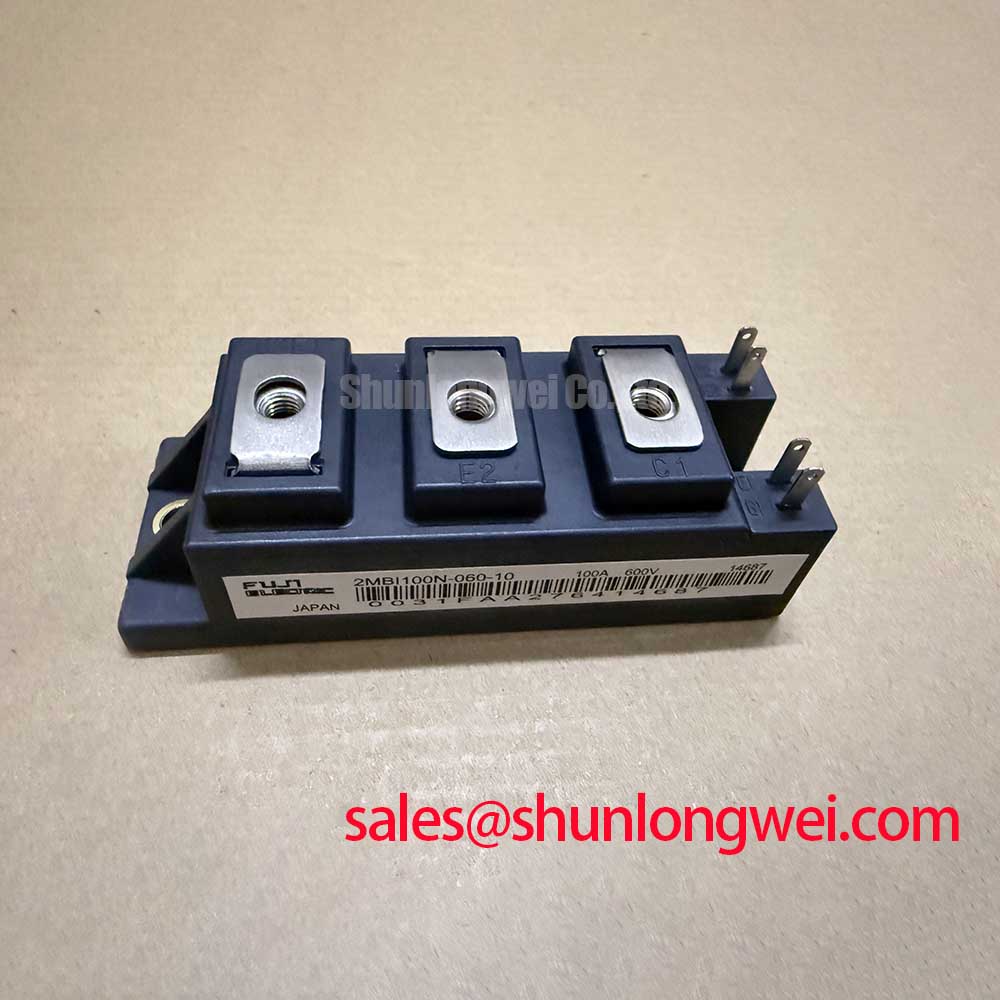
The CM100DY-12E page can be reviewed as a neutral cross-model reference when the equipment documentation identifies a different Mitsubishi Electric power module. It should not be treated as an automatic substitute for the PM100RSA060. Voltage class, current capability, package geometry, gate-drive behavior, protection interface, and system qualification all require separate confirmation.
Assembly Integrity and Junction-to-Case Thermal Evaluation
Thermal investigation should begin with the physical heat path. Remove contamination from the heatsink, inspect the contact surface for distortion or foreign material, and check whether the thermal interface material has hardened, migrated, or separated. The PM100RSA060 has a specified current rating of 100.0 A, but that number does not independently define allowable continuous current in a finished machine. Load duty, switching frequency, ambient temperature, airflow, heatsink impedance, overload duration, and control strategy determine the junction temperature result.
A junction-to-case simulation should therefore use the thermal resistance and transient thermal impedance data from the applicable Mitsubishi Electric technical documentation. If a multi-RC model is used, each RC branch should be identified from the manufacturer’s published thermal response rather than estimated from a generic IPM model. The simulated junction temperature must then be compared with measured case temperature and the actual load waveform. Without the relevant thermal curves, a numerical junction-temperature margin should not be assigned to this product page.
For inverter welding equipment, phase-angle or pulse conduction control can create a nonuniform thermal pattern even when average output power appears stable. Medium-frequency induction-heating systems can also produce repeated current bursts that stress the thermal path differently from a steady industrial load. The commissioning record should include the real duty cycle, switching behavior, heatsink temperature, fan or coolant condition, and the duration of the hottest operating sequence.
Line-frequency ripple smoothing and DC-link stability should be reviewed together with the module temperature. A poorly controlled ripple current can increase electrical and thermal stress, while an RC snubber can reduce ringing but add its own dissipation. These are Design Considerations for the converter, not guaranteed operating features of the PM100RSA060.
⚠️ Maintenance Note: Schedule heatsink cleaning and thermal-interface inspection according to the equipment environment, then monitor contact temperature and verify that the cooling path remains unobstructed during commissioning.
Terminal fastening should be checked with the equipment manufacturer’s specified procedure and calibrated tooling. Do not infer a module-specific mounting torque, grease thickness, or clamping sequence from a generic package guide. Excessive mechanical force can distort the base or terminal area, while insufficient force can increase contact resistance and local heating. The final assembly method must follow the applicable Mitsubishi Electric mechanical documentation and the host equipment service manual.
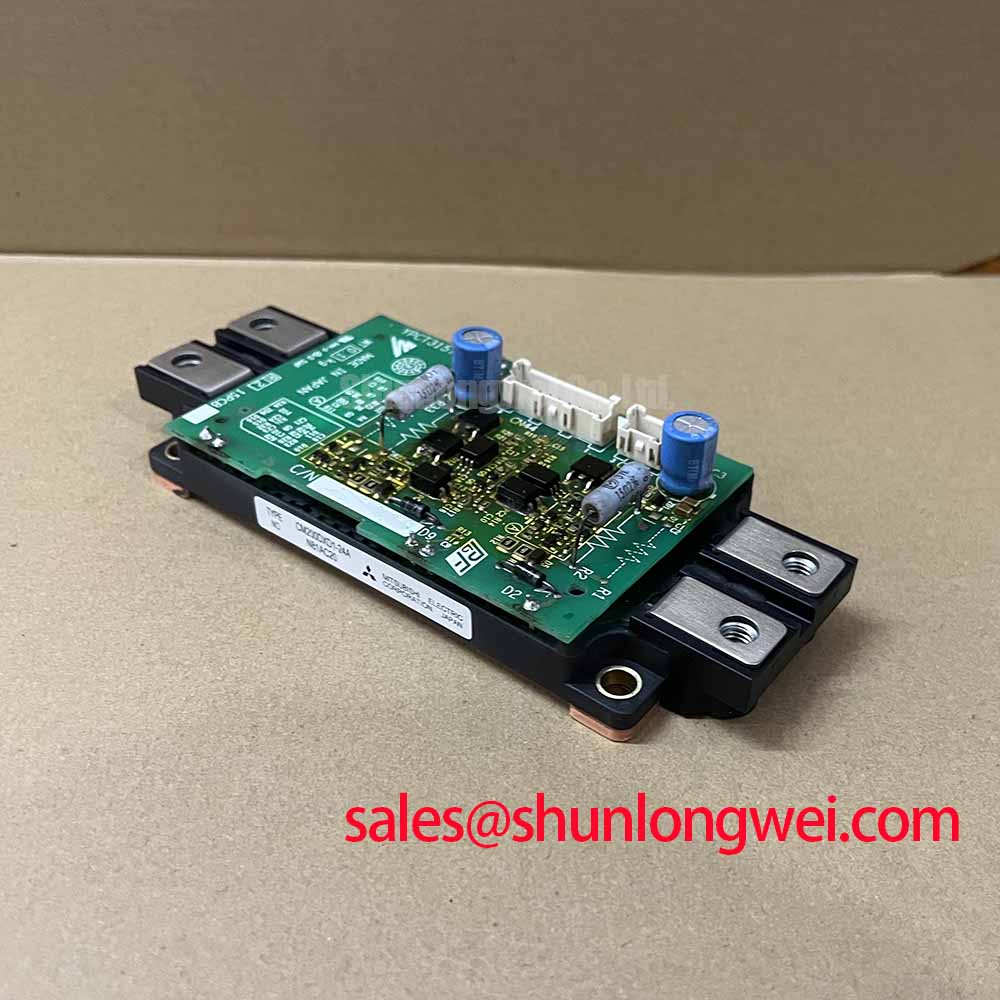
For a front-end or complementary power-stage review, engineers may also examine the CM300DXDX1-24A product information as a separate topology reference. Its presence in a system architecture does not establish compatibility with the PM100RSA060. The rectifier stage, DC-link design, inverter stage, protection circuits, and cooling system should be assessed as a complete chain.
Control-Interface Integration and Capacitive Coupling
Control-interface evaluation is required before applying the full DC-link voltage. High-voltage switching can couple energy into the control circuit through device capacitances and board parasitics. This may appear as unwanted switching, abnormal switching overlap, ringing, or a protection trip, but none of these symptoms proves a single failure mechanism. Check the control-input signal at the module interface with a measurement method suitable for the isolation arrangement, then compare it with the controller command and the corresponding phase-leg waveform.
Active Miller-clamp circuits, negative gate bias, split gate resistance, and other gate-control methods are system-level options for designs with accessible gate-drive circuitry; they should not be assumed to be external control options for this IPM. The PM100RSA060 listing does not provide sufficient official data to prescribe a control method or to assign a specific negative voltage. Designers should verify the control-input requirements, driver supply range, protection thresholds, dead-time requirements, and switching conditions from the Mitsubishi Electric documentation that applies to the exact device revision.
Keep the external control-signal path compact and route the command and return conductors as a controlled pair. Avoid running sensitive control traces alongside high-current collector or emitter paths for long distances. If the control board is mounted remotely, evaluate the effect of connector inductance, isolation capacitance, common-mode displacement current, and cabinet grounding. A control signal that is clean on the bench may change after the cable harness, heatsink, and enclosure are installed.
When a protection circuit operates during a switching test, inspect the control supply, isolation barrier, desaturation or overcurrent feedback if present, input wiring, and measurement setup before replacing the module. A controlled low-energy test with a verified current limit is preferable to repeated full-power attempts. Record the turn-on and turn-off waveforms at the same probe locations so that changes can be separated from instrumentation error.
For additional design context, the Precision Gate Drive Design resource can be used when reviewing switching control and measurement practice. It is a general engineering reference and does not replace Mitsubishi Electric’s product-specific limits. Further semiconductor information is available through Mitsubishi Electric Global Semiconductor Device Technologies.
Field Diagnostics and Commissioning of the PM100RSA060 Topology
Commissioning should proceed from passive inspection to low-energy switching and then to the intended operating profile. Confirm the module identity, inspect the package and terminals, document the original wiring, and verify the DC-link isolation state before connecting the control harness. The replacement decision should be based on electrical ratings, mechanical fit, terminal compatibility, control behavior, and the thermal design rather than on the 600 V and 100 A markings alone.
Where the module documentation provides separate power and control return paths, keep the high-current return physically distinct from the sensitive control-signal return and follow the documented terminal arrangement. Do not assume that every IPM uses the same return or feedback configuration. The system integrator should verify the actual pinout from the original Mitsubishi Electric documentation and confirm continuity with the host control board before applying control power.
Oscillation or uneven phase behavior can result from several conditions, including excessive loop area, poor return routing, unstable control supply, incorrect dead time, probe influence, grounding errors, or a damaged switching path. Use a known-good phase as the comparison reference. Check the control-input waveform, power-device terminal waveform, current sensor output, protection feedback, and DC-link ripple under the same test conditions. This approach provides objective evidence without assigning a single cause from one symptom.
In industrial inverter welders, verify that the output transformer, current sensor, cooling system, and control sequence are ready before increasing load. In medium-frequency induction-heating equipment, review the resonant network, work-coil connection, current feedback, and startup sequence as part of the compatibility assessment. The PM100RSA060 can be evaluated for these equipment classes when its complete electrical and mechanical requirements match the host design; the product category alone is not an application guarantee.
After commissioning, retain the measured switching waveforms, case-temperature record, alarm history, fastening record, and cooling inspection notes with the equipment maintenance file. This makes later diagnosis more reliable when a load profile, controller revision, or enclosure condition changes. Any operating limit not explicitly stated in the confirmed product data should be obtained from the applicable manufacturer documentation or established through a controlled system qualification process.