Content last revised on September 22, 2026
Preventing Spurious Faults: Multi Module Parallel Current Sharing Guidelines for PM200CBS060
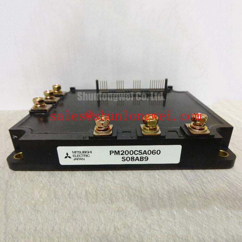
Before installation, verify the nameplate and cold state condition of the replacement against the original assembly: PM200CBS060 is identified as a Mitsubishi Electric IPM module with an official rated voltage of 600.0 V and an official rated current of 200.0 A. Inspect the housing, power terminals, control terminals, mounting surface, and thermal interface before applying the DC link.
| Manufacturer | Mitsubishi Electric |
| Model | PM200CBS060 |
| Product category | IPM Module |
| Rated voltage | 600.0 V, official specification |
| Rated current | 200.0 A, official specification |
| Typical evaluation | Heavy duty variable frequency AC motor drive, subject to system verification |
The electrical ratings identify the component class, but they do not by themselves establish suitability for every inverter topology, switching frequency, overload profile, cooling arrangement, or control board. When evaluating a replacement in an industrial drive, engineers should compare the original gate drive requirements, protection sequence, terminal assignment, mechanical interface, and thermal path with the equipment documentation.
Parallel operation requires more than connecting corresponding power terminals together. In a practical inverter, static current sharing is influenced by the on state voltage behavior of each switching path, while dynamic sharing is strongly affected by gate loop inductance, driver propagation delay, stray capacitance, and the physical symmetry of the commutation paths. The positive temperature behavior commonly associated with IGBT conduction voltage can support a stabilizing tendency during steady state operation, but this should be verified against the actual electrical characteristics supplied for the selected module and operating condition.
For a PM200CBS060 installation involving parallel current paths, keep the gate driver arrangement physically symmetrical. Route the gate and emitter return conductors with comparable length and impedance, and avoid allowing one module to share a long common return section with another. The main power conductors should also present comparable resistance and inductance. A layout that looks symmetrical on a schematic may still produce unequal switching behavior if one module is mounted farther from the DC link capacitor or has a different busbar overlap.
Commissioning should begin with low energy testing and a known safe DC link condition. Observe the gate to emitter waveform at each module using measurement equipment with suitable common mode capability. Compare turn on delay, turn off behavior, ringing, and the voltage across each switching path. A difference in waveform shape does not identify one single fault automatically; it may reflect driver mismatch, parasitic coupling, probe placement, busbar geometry, or a damaged control interface. The correct response is to compare the suspect path with a known good path while keeping the measurement reference consistent.
Clearance around the high voltage bus, gate driver wiring, and control connector should follow the applicable equipment insulation design and local safety requirements. Do not reduce spacing simply because the module itself fits a smaller mechanical envelope. Designers should also check whether parallel modules require individual gate resistive control, separate fault feedback treatment, or a coordinated protection sequence. These are system decisions and should be validated during switching tests rather than inferred from the current rating alone.
For a wider review of gate drive arrangement, thermal paths, and power circuit topology, engineers can consult IGBT Design & Integration. The related CM100DY 12E may also be reviewed as a Mitsubishi Electric power module for comparison, subject to the original equipment design and documented electrical conditions.
PM200CBS060 Circuit Protection and Reliability: Calibrating Differential Gate Source Loop Routing
Gate loop routing deserves direct inspection whenever a drive shows intermittent overcurrent trips, uneven switching, or unexplained gate waveform oscillation. The auxiliary emitter return used by the driver should be separated from the high current emitter path as far as the module terminal arrangement and equipment design permit. This arrangement reduces the influence of voltage developed by load current in the main emitter conductor. If the driver senses its reference through a section carrying rapid load current changes, the gate source voltage seen by the control circuit may differ from the intended device reference.
This is a Design Consideration, not an additional factory rating for PM200CBS060. The final connection method must follow the Mitsubishi Electric application documentation and the original drive schematic. Engineers should inspect the complete loop from driver output, through the gate conductor, into the module terminal, and back through the intended emitter reference. Keep the power commutation loop and gate control loop clearly identifiable during inspection. Avoid routing sensitive control wires alongside high di/dt busbar edges unless the insulation, spacing, and shielding method have been evaluated.
The thermal interface is equally important. Remove aged or uneven thermal compound, inspect the heatsink for contamination or distortion, and apply the interface material according to the equipment or module assembly specification. A film that is too thick can increase thermal resistance, while incomplete coverage can create local hot regions. The correct thickness and material are installation variables that should be controlled by the maintenance procedure rather than guessed from the module current rating.
Mounting pressure should be applied in the sequence and torque specified by the equipment manufacturer or Mitsubishi Electric documentation. Where a cross pattern is required, bring the fasteners down progressively so the module base is not forced into angular contact with the heatsink. Maintenance Note: After commissioning, monitor contact temperature under a repeatable load and recheck the cooling path for dust, blocked airflow, and condensation exposure.
Terminal inspection should include discoloration, looseness, damaged threads, and evidence of thermal cycling. A visual check is not sufficient for a suspected intermittent connection; isolate the equipment, follow the site electrical safety procedure, and verify continuity and mechanical condition with the appropriate instruments. The module should not be inserted or removed while energized, and the DC link discharge state must be confirmed before service.
PM200CBS060 Circuit Protection and Reliability: Calibrating High Frequency Common Mode Bearing Current
Long motor cables can behave as transmission structures rather than simple low impedance connections. Fast inverter edges may reflect at the motor terminals when the cable, motor, and output network have different characteristic impedances. The resulting terminal voltage can exceed the local inverter waveform and, in some installations, approach twice the incident step amplitude. This is a system level behavior, not an additional PM200CBS060 output specification.
When a heavy duty variable frequency AC motor drive produces bearing current, motor frame current, cable shield heating, or unexplained common mode noise, begin by recording the motor cable length, shield termination arrangement, grounding structure, motor construction, switching pattern, and output filter configuration. Use a measurement method suitable for the common mode voltage and verify that the probe connection does not create an artificial loop. A waveform captured at the inverter terminals may not represent the voltage at the motor terminals.
Output chokes, dv/dt filters, sinusoidal filters, common mode cores, and cable shield arrangements can address different parts of the problem. Selection should be based on the complete drive and motor combination, including switching behavior, cable construction, motor insulation limits, control response, and thermal loading. Designers should verify the resulting peak voltage and current against the equipment limits during controlled testing. A filter selected only by motor power or inverter current may introduce unwanted resonance or alter the protection response.
The PM200CBS060 rating of 600.0 V and 200.0 A provides the official component identification boundary supplied for this product page. It does not certify a complete motor cable installation for EMC, insulation stress, or bearing current performance. Mitsubishi Electric publishes power semiconductor and high power module information through its Power Semiconductors and High Power Modules resource, which should be read together with the exact module documentation and drive manual.
During fault investigation, compare the inverter output waveform before and after the filter, then inspect the motor end and protective earth path. If the symptom changes with cable routing, shield bonding, or switching command, that may indicate a common mode coupling or impedance interaction rather than a defective power module. The module should only be condemned after the gate signal, supply sequence, protection feedback, cooling condition, and power circuit have been checked.
Transient Dynamics and Electrical Design: Reinforced Insulation Barrier Integrity on PM200CBS060
High voltage isolation must be evaluated from the complete assembly, not from the IPM label alone. The supplied product information confirms the 600.0 V voltage class, 200.0 A current class, and Mitsubishi Electric IPM module category, but it does not provide a verified reinforced insulation withstand value or a confirmed common mode transient immunity value for this page. Claims such as insulation above 5 kV or immunity above 100 kV per microsecond should therefore not be treated as PM200CBS060 factory specifications without the applicable official datasheet or test report.
Inspect the physical separation between the DC link, output terminals, gate control wiring, heatsink, chassis, and protective earth. Creepage and clearance are determined by working voltage, pollution environment, material group, altitude, overvoltage category, and the applicable product standard. The final spacing must be established by the system designer and verified against the equipment safety file. Do not infer an insulation rating from the molded housing size or from a successful low voltage bench test.
Common mode transients can couple through parasitic capacitance between power conductors, heatsinks, control wiring, and enclosure metalwork. Practical controls include minimizing unnecessary loop area, separating high dv/dt conductors from sensitive feedback wiring, maintaining a deliberate return path, and validating the gate signal at the module terminals. If a false gate pulse is suspected, compare the command signal, driver output, local emitter reference, fault feedback, and auxiliary supply during the same switching event.
For field service, record the original wiring before removal and verify every control connection against the equipment schematic. Check that isolation monitoring, interlock logic, and undervoltage protection operate in the intended sequence. A nuisance trip may result from wiring reference error, insufficient decoupling, measurement coupling, or a genuine module fault; the available evidence should distinguish these possibilities before replacement.
Engineers evaluating a direct replacement should compare the original mechanical outline, terminal arrangement, control interface, protection logic, and cooling method rather than relying on voltage and current ratings alone. The CM300DXDX1 24A can be reviewed as a related Mitsubishi Electric module for objective replacement assessment, but compatibility remains dependent on the original equipment design and documented electrical conditions.