Content last revised on September 17, 2026
PM20CHA060 Inspection and Specifications
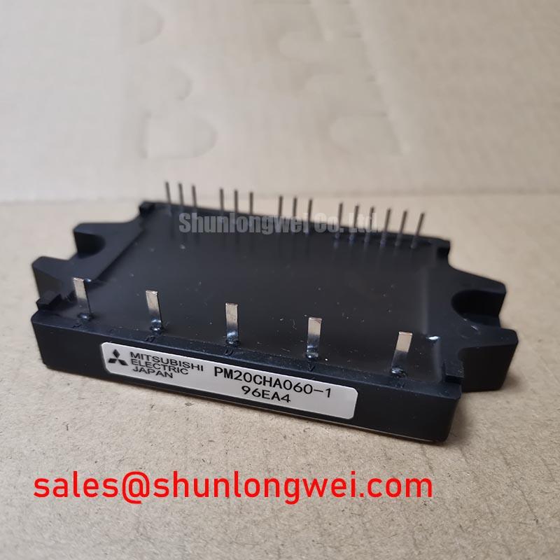
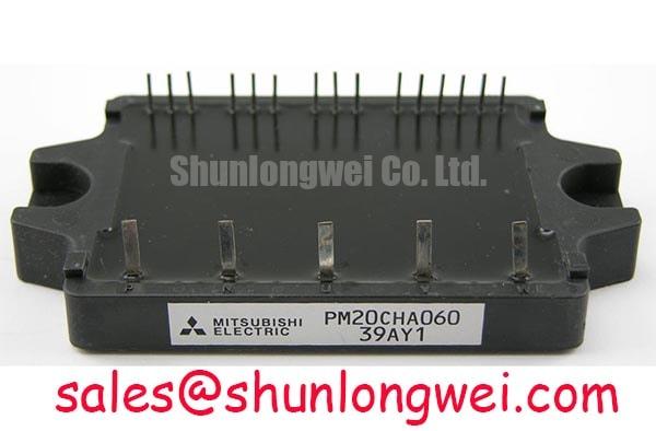
With the DC link discharged and isolated, begin incoming inspection by confirming that the PM20CHA060 power terminals show no unintended low-resistance path and that the nameplate rating matches the equipment record before reconnecting any control wiring. The PM20CHA060 is a Mitsubishi Electric intelligent power module specified at 600 V collector-emitter voltage, 20 A collector current at TC = 25 degrees C, and 40 A peak collector current. These are Official Datasheet Specifications and establish the electrical boundary that a repair engineer should verify against the original servo drive or motion actuator design.
The module has an Official Datasheet Specification of 62 W collector dissipation at TC = 25 degrees C, a 400 V protection-related voltage parameter at Tj = 125 degrees C, and 2500 Vrms isolation voltage for one minute AC. These values describe the component rating, not a complete system approval or a universal operating prescription. In a precision stepper or BLDC servo motion actuator, the control board, DC link, thermal interface, motor cable, protection sequence, and enclosure arrangement must be assessed together.
| Official Specification | Symbol | Value | Condition |
|---|---|---|---|
| Collector-emitter voltage | VCES | 600 V | Official Datasheet Specification |
| Collector current | IC | 20 A | TC = 25 degrees C |
| Peak collector current | ICP | 40 A | Official Datasheet Specification |
| Collector dissipation | PC | 62 W | TC = 25 degrees C |
| Protection-related voltage parameter | VCC(PROT) | 400 V | Tj = 125 degrees C |
| Isolation voltage | Viso | 2500 Vrms | AC, 1 minute |
Bench Tip: Use ESD-controlled handling and record cold-state terminal readings alongside a known-good board or approved service reference, because a diode-mode observation is a comparison tool rather than a standalone pass or fail verdict.
PM20CHA060 Operational Boundaries: Evaluating DC-Link Capacitance Bank Layout and Low-ES Limits
For a PM20CHA060 installation, the first layout check is the physical path joining the DC-link capacitor bank, the module power terminals, and the return conductor. At turn-off, the voltage seen by the switching path rises above the DC-link level by an amount related to stray inductance and current change rate. In engineering terms, peak voltage follows the DC-link voltage plus the inductive contribution produced by loop inductance multiplied by di/dt. This relationship is an Engineering Calculation principle, not a declared PM20CHA060 switching limit.
A short, broad, closely coupled supply-and-return current path is a Design Consideration for suppressing inductive overshoot. A laminated or planar busbar arrangement can reduce loop area when compared with separated conductors, but the actual result depends on conductor geometry, capacitor terminal locations, assembly tolerances, and switching conditions. The system engineer should measure switching waveforms at the installed DC-link voltage and load condition, then confirm that peak voltage remains compatible with the 600 V VCES Official Datasheet Specification.
Place the intended high-frequency DC-link energy storage close to the commutation path, while retaining the bulk capacitance needed by the wider drive system. A capacitor positioned remotely on a wiring harness can support average DC-link energy but may not control the local transient loop effectively. Oscilloscope probing must also be planned carefully: an extended ground lead can add pickup and make a ringing event appear more severe or different in frequency than the actual module-terminal waveform.
When a waveform shows repeated overshoot, ringing, or uneven phase behavior, inspect capacitor connections, busbar alignment, joint cleanliness, and the proximity of the return path before attributing the condition to the module. A snubber capacitor or damping network may be evaluated as a Design Consideration, with capacitance, damping, voltage rating, heat dissipation, and placement determined from measured waveforms. The component data provided here does not establish a universal snubber value.
For drive architectures that pair an inverter stage with a separate rectifier function, engineers sometimes evaluate related power hardware such as the CM300DXDX1-24A in the broader rectification topology. Electrical function, voltage class, current capability, thermal path, terminal arrangement, and control architecture require independent confirmation; a related module is not automatically a replacement for the PM20CHA060.
Assembly Integrity & Layout Architecture: Implementing Negative Gate Bias vs Active Miller Clamping for PM20CHA060
Before considering negative gate bias or an active Miller clamp, determine the control interface actually available on the original PM20CHA060 installation. This product is identified as an intelligent power module, and the supplied official parameters do not define accessible individual gate terminals, gate-drive voltage limits, a required negative bias, or an active-clamp interface. Those functions must therefore not be represented as official settings for this part.
Negative gate bias and active Miller clamping are Design Considerations used in some externally driven IGBT arrangements to resist false turn-on caused by rapid collector voltage movement. Whether either approach applies depends on the specific module interface, original control board, gate-driver circuit, isolation arrangement, and documented manufacturer requirements. A service engineer should retain the original driver topology unless verified documentation and controlled bench testing establish that a change is appropriate.
The same physical power-loop discipline remains relevant even when control circuitry is internal to the module. Keep commutation conductors compact and paired, minimize parasitic inductance, and position any intended suppression parts according to measured current-loop behavior. These measures address turn-off inductive overshoot and conducted switching disturbance, but they do not constitute a claim of standalone EMC compliance for the PM20CHA060.
Check mounting surfaces for flatness, contamination, trapped debris, and uneven pressure. Apply thermal interface material according to the equipment service documentation and the thermal compound supplier guidance. Field Alert: Disconnect, discharge, and verify the DC link before fitting or removing module connections, because stored energy can remain present after the controller has been switched off.
The 2500 Vrms isolation voltage for one minute AC is an Official Datasheet Specification. It should be reviewed against the service design's isolation requirement, but it does not replace an equipment-level insulation coordination review. Avoid improvised high-voltage tests that exceed the original procedure, since test configuration, applied waveform, creepage paths, and connected circuitry affect the result.
Benchtop Waveform Tuning: Mitigating Stress via Thermal Feedback on PM20CHA060
Benchtop verification should begin with static checks and then progress to controlled energized testing only after the original terminal mapping, supply polarity, mechanical attachment, and protection wiring have been confirmed. Compare phase currents, DC-link behavior, and switching waveforms under repeatable operating conditions. A current imbalance, noise burst, or temperature difference may arise from several locations, including sensor scaling, motor-cable connections, controller timing, cooling performance, mechanical load, or the power stage itself.
IGBT conduction behavior can exhibit a positive temperature tendency that supports steady-state current sharing in appropriately designed parallel arrangements. This is a Design Consideration, not a declaration that any PM20CHA060 parallel connection will share current safely. Dynamic sharing still depends heavily on symmetric conductor paths, matched timing, current-loop geometry, common thermal conditions, and coordinated protection. System engineers should validate dynamic balance using the intended control hardware and representative load transitions.
For a precision stepper or BLDC servo motion actuator, record the baseline DC-link voltage, output current, heatsink temperature trend, and motor response before making one change at a time. This helps distinguish an intermittent control signal issue from a power-loop issue. If switching traces differ between phases, compare probe connection method and measurement location first, then examine power-terminal joints and the controller's command and feedback paths against a known-good signal path.
The protection-related voltage specification of 400 V at Tj = 125 degrees C should be treated as an Official Datasheet Specification requiring context from the original circuit. It does not identify a user-adjustable protection threshold, nor does it establish an external gate-driver supply requirement. For bootstrap-related driver circuits in compatible system designs, Mitsubishi Electric's DIPIPM Bootstrap Circuit Design note provides a useful reference for reviewing charge and recharge behavior. The original drive documentation remains the controlling source for the PM20CHA060 implementation.
When evaluating a damaged motion controller, retain evidence from measured waveforms, terminal checks, thermal observations, and fault history. The practical test and failure-analysis methods collected in the Field Engineer's Handbook can support a structured assessment of peak-voltage margin, connection integrity, and test safety without assigning a single unverified cause to a symptom.
PM20CHA060 Thermal-Electrical Optimization: Dynamic Braking Chopper Operation Practical Tuning
Dynamic braking requires special attention because motor deceleration returns kinetic energy toward the DC link. In a servo actuator, the braking path may involve an internal function or a separately arranged braking IGBT and ballast resistor. The supplied PM20CHA060 official parameters do not confirm an internal braking transistor, braking-resistor connection, resistor value, or chopper threshold. The repair engineer should verify the original schematic and module terminal documentation before making any assumption about that function.
A braking resistor is selected at system level to absorb regenerative energy while remaining within the resistor's pulse-energy, average-power, insulation, enclosure-temperature, and duty-cycle limits. The braking switch, resistor, DC-link capacitance, motor inertia, commanded deceleration, and controller protection behavior form one system. An Engineering Recommendation is to validate the DC-link waveform during the highest credible deceleration event, then review measured thermal behavior over the required duty cycle. No fixed braking-resistor value can be derived from the PM20CHA060 ratings alone.
Thermal assessment should connect electrical observations to the mounting condition. The 62 W PC at TC = 25 degrees C value is an Official Datasheet Specification with a stated case-temperature condition, not a guarantee of dissipation in a finished cabinet. Heatsink temperature, airflow, thermal interface coverage, mounting pressure, switching activity, and neighboring heat sources all influence operating temperature. Compare temperature trends at the same test point and operating profile when assessing repairs or production substitutions.
If the drive's DC-link voltage rises unexpectedly during stopping, inspect the commanded deceleration profile, brake-control signal, resistor continuity, resistor mounting condition, DC-link capacitance, and power-return routing. An open resistor circuit, unsuitable brake command, weak DC-link connection, or measurement error can each contribute. The correct next step is controlled measurement against the original equipment documentation, not an inferred change to module limits.
Where a separate rectifier module is used upstream, consult the relevant device documentation and system topology when reviewing regenerative paths. Mitsubishi Electric's diode modules lineup is a reference point for identifying diode-module families, while actual compatibility remains dependent on the original circuit, voltage rating, current duty, cooling arrangement, and mechanical connections.