

Content last revised on June 18, 2026
Engineering the Future of Compact Drives: A Technical Analysis of the PM25RL1B120 Intelligent Power Module
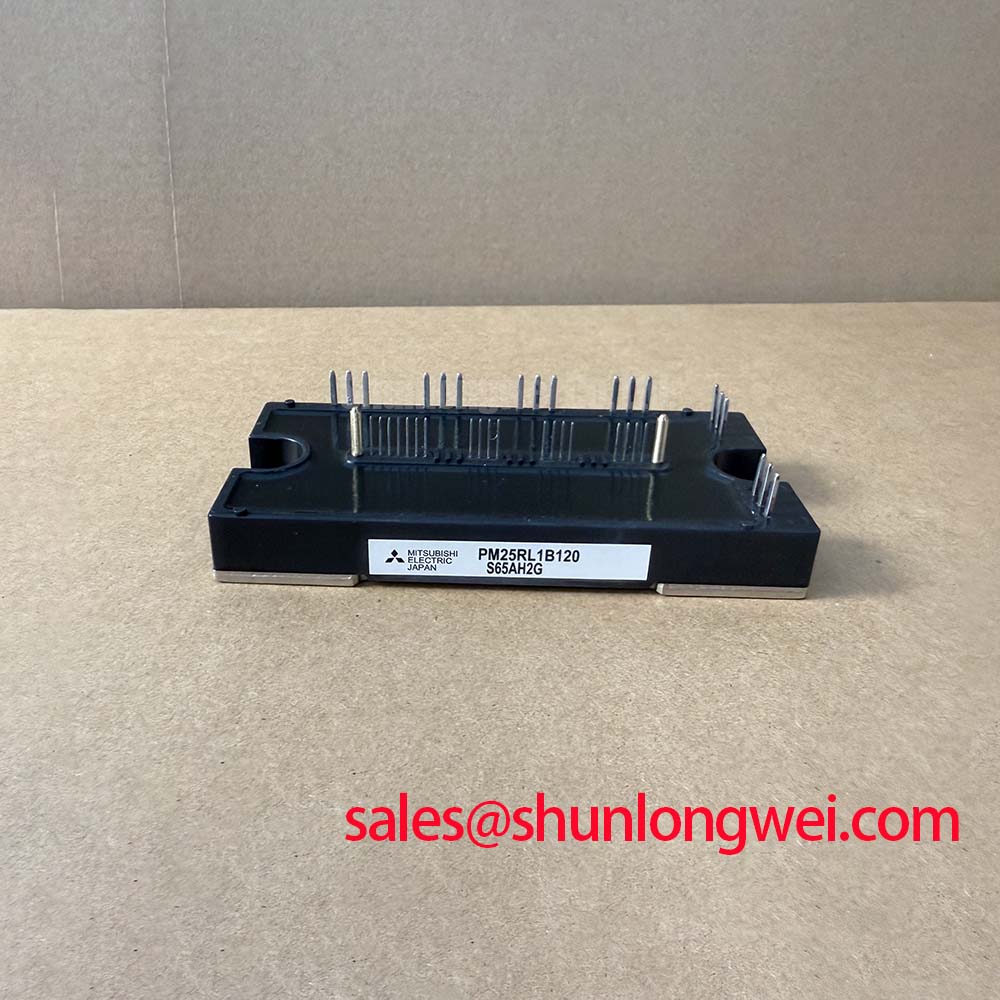
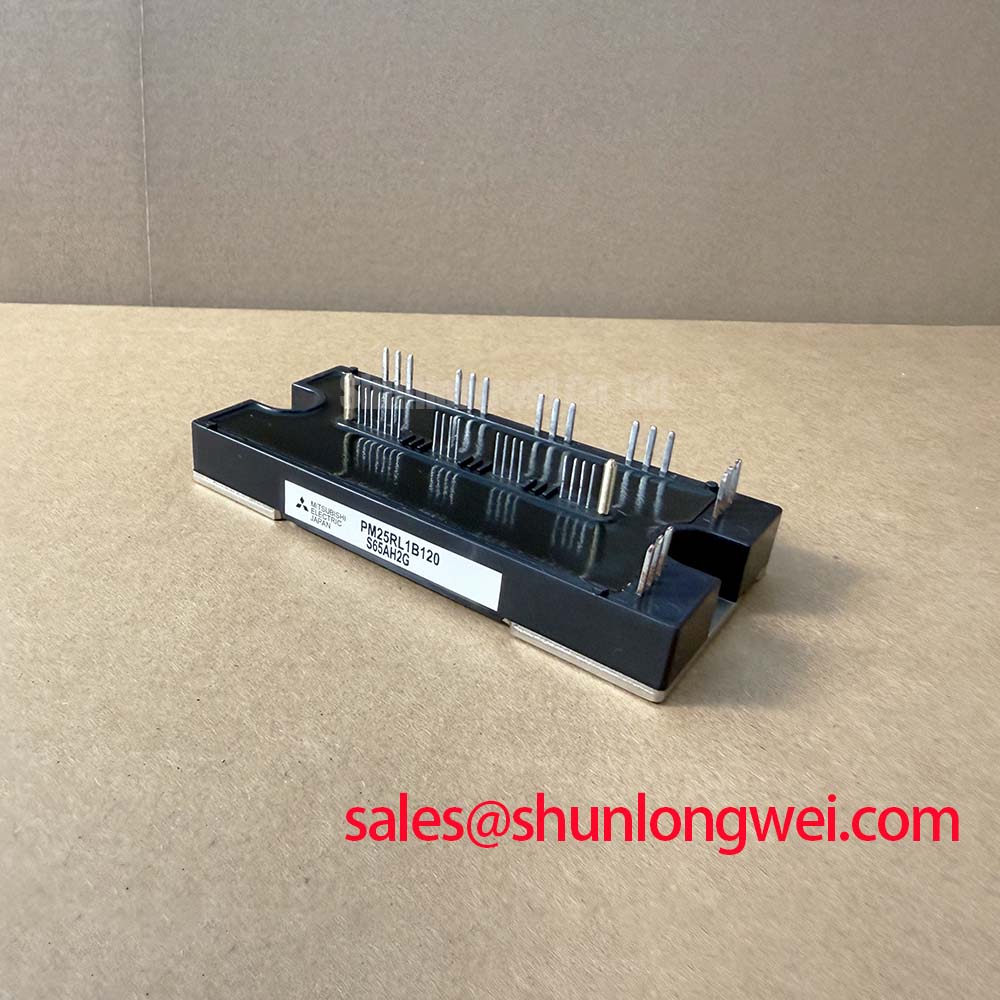
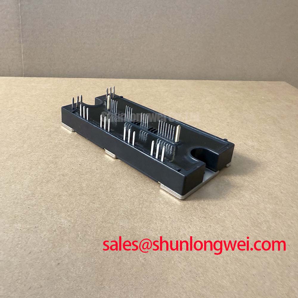
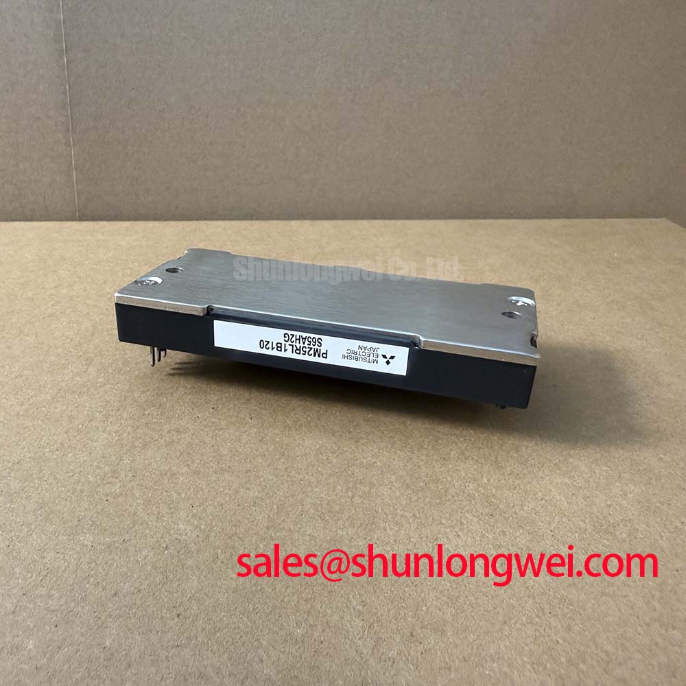
The PM25RL1B120, manufactured by Mitsubishi Electric, represents a sophisticated milestone in the evolution of power electronics, specifically within the Intelligent Power Module (IPM) category. By integrating a three-phase inverter bridge, a brake circuit, and advanced drive/protection logic into a single L1-Series package, this module provides engineers with a robust foundation for high-performance motor control. Its 1200V / 25A rating is meticulously calibrated for industrial applications where space constraints and reliability are non-negotiable.
UVP: Fail-Safe Precision through Integrated Gate Drive and Real-Time Fault Protection Logic.
- Top Specs: 1200V Vces | 25A Ic | 2.5kV Isolation Voltage.
- Key Benefits: Reduces peripheral component count; enhances system-level MTBF.
- Core Question Answered: How does the PM25RL1B120 improve reliability compared to discrete designs? It eliminates the risks of improper gate drive layout and provides sub-microsecond response times for short-circuit and over-temperature faults that external controllers cannot match.
For designers prioritizing thermal efficiency and reduced footprint in 400V AC systems, the PM25RL1B120 stands as the optimal choice.
Key Parameter Overview
Decoding the Specs for Enhanced Thermal Reliability
The following technical data is derived from the official Mitsubishi Electric specifications. Understanding these values is critical for determining the safe operating boundaries and thermal management requirements of the system.
| Functional Group | Parameter Symbol | Typical Value / Rating |
|---|---|---|
| Inverter Part | Collector-Emitter Voltage (Vces) | 1200V |
| Inverter Part | Collector Current (Ic) | 25A (at Tc=25°C) |
| Brake Part | Collector Current (Ic) | 15A |
| Control Part | Supply Voltage (Vd) | 15V (13.5V to 16.5V) |
| Thermal Resistance | Rth(j-c)Q (IGBT) | 0.95 °C/W (Max) |
| Isolation | Viso (60Hz, 1 min) | 2500V |
Download the PM25RL1B120 datasheet for detailed specifications and performance curves.
Application Scenarios & Value
Optimizing Performance in Precision Servo and General-Purpose Drives
In high-performance Variable Frequency Drive (VFD) environments, engineers often face the challenge of managing back-EMF during rapid deceleration. The PM25RL1B120 solves this via its integrated Brake Circuit, which can handle a peak current of 15A. This feature is essential for "snubbing" excess energy in high-inertia industrial conveyor systems, preventing overvoltage trips without requiring external braking transistors.
Consider a Servo Drive application requiring frequent start-stop cycles. The PM25RL1B120's low Vce(sat) (typically 1.8V) minimizes conduction losses, directly translating to a cooler-running module. This thermal headroom allows for a more compact heatsink design, which is vital for multi-axis robotic controllers where DIN-rail space is at a premium. Furthermore, the integration of Under-Voltage Lockout (UV) and Short-Circuit (SC) protection ensures that the silicon remains protected even during transient power fluctuations or wiring errors in the field.
For systems requiring higher current handling within the same architecture, the PM75CL1B120 offers a higher current rating while maintaining the same 1200V voltage class. Understanding the trade-offs between integration and discrete components is vital; for a detailed framework, refer to our guide on IPM vs Discrete IGBT Strategic Selection.
Technical Deep Dive
The "Silicon Bodyguard": Understanding Integrated Protection Logic
The defining characteristic of the PM25RL1B120 is its internal control architecture. Traditional power modules require an external gate driver with complex isolation and protection circuits. This module, however, integrates these functions directly onto the chip-carrier. Think of the internal logic as a "Silicon Bodyguard"—it monitors the operating state 25,000 times a second, far faster than any software-based routine in a PLC or MCU.
A critical parameter here is the Thermal Resistance (Rth(j-c)) of 0.95 °C/W for the IGBT portion. This is analogous to a wide, clear highway for heat; it allows thermal energy to move from the junction to the case with minimal "traffic congestion." When coupled with the integrated Over-Temperature (OT) protection—which triggers a fault signal at a case temperature of approximately 100°C to 120°C—the module effectively self-polices to prevent catastrophic failure. This hardware-level protection is a primary reason why Intelligent Power Modules are favored in remote industrial installations where maintenance access is limited. To prevent common failures in such high-power environments, engineers should consult our IGBT failure analysis resource.
Frequently Asked Questions
How does the integrated short-circuit protection in the PM25RL1B120 function during a phase-to-ground fault?
The module utilizes a dedicated current-sensing emitter on each IGBT. When the current exceeds the threshold, the internal drive circuit performs a "soft shut-down" and outputs a Fault (Fo) signal to the host controller, typically within 1-2 microseconds, preventing silicon meltdown.
What are the recommended gate drive supply requirements for the PM25RL1B120 to ensure optimal switching?
A stable 15V DC supply (with a tolerance of +/- 1.5V) is required for each of the four isolated control power supplies (three for the high side, one for the low side). Using a low-impedance capacitor near the module pins is essential to filter high-frequency switching noise.
Can the PM25RL1B120 be used without an external brake resistor?
No. While the module contains the Brake IGBT, an appropriately sized external power resistor must be connected to dissipate the energy. The internal circuit simply acts as the high-speed switch to control the energy flow into that resistor.
For further insights into the Mitsubishi CSTBT™ technology used in these modules, visit the Mitsubishi Electric Motion Control Portal.