Content last revised on January 20, 2026
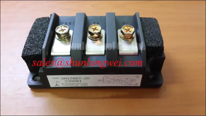
QM150DY-2H Datasheet: IGBT Module for Efficient Power Switching
Technical Deep Dive: Balancing Conduction and Switching Losses
The Mitsubishi QM150DY-2H is an H-Series IGBT module engineered to reduce total power dissipation in high-frequency switching applications. It delivers a strategic balance of low conduction and switching losses, a critical factor in the design of efficient power conversion systems. With core specifications of 1000V and 150A, this module provides a robust foundation for demanding industrial loads. Its low VCE(sat) directly curtails heat generated during on-state operation, which simplifies thermal management and can lead to smaller heatsink requirements. For engineers grappling with efficiency targets, the QM150DY-2H's electrical characteristics offer a direct path to minimizing wasted energy and improving system reliability.
A Datasheet-Driven Look at Key Electrical Ratings
The performance of the QM150DY-2H is defined by its precise electrical and thermal characteristics. These parameters, drawn directly from the official datasheet, provide the necessary data for system modeling, thermal simulation, and reliability assessment. Understanding these specifications is the first step in integrating this module successfully into any high-power design. For systems requiring a different voltage or current profile, the CM300DY-24H offers higher current handling capabilities.
| Parameter | Symbol | Conditions | Value | Unit |
|---|---|---|---|---|
| Collector-Emitter Voltage | VCEX | VEB = 2V | 1000 | V |
| Collector Current (DC) | IC | - | 150 | A |
| Collector-Emitter Saturation Voltage | VCE(sat) | IC = 150A, IB = 1.5A | 2.7 (Max) | V |
| DC Current Gain | hFE | IC = 150A, VCE = 5V | 75 (Min) | - |
| Turn-On Time | t(on) | VCEX = 600V, IC = 150A, IB1 = 1.5A | 4.0 (Max) | µs |
| Turn-Off Time | t(off) | VCEX = 600V, IC = 150A, IB2 = -3.0A | 3.0 (Max) | µs |
| Parameter | Symbol | Conditions | Value | Unit |
|---|---|---|---|---|
| Thermal Resistance (Junction to Case) | Rth(j-c) | Transistor part, Per 1/2 Module | 0.16 (Max) | °C/W |
| Operating Junction Temperature | Tj | - | -40 to +150 | °C |
| Isolation Voltage | Viso | AC for 1 minute | 2500 | V |
Download the Datasheet for comprehensive specifications and performance curves.
Application Arenas Where Efficiency Prevails
The QM150DY-2H module is tailored for power electronics where minimizing energy loss is a primary design objective. Its characteristics make it a strong candidate for a range of high-power control systems.
Key Application Fields
- Industrial Motor Drives: In Variable Frequency Drives (VFDs) and servo systems, the module's low VCE(sat) translates to higher inverter efficiency and reduced operating temperatures, enhancing the longevity of the drive.
- Power Conversion Systems: Suitable for the core switching stage in uninterruptible power supplies (UPS) and industrial power converters, where reliability and efficiency are crucial for operational continuity.
- Welding Equipment: The module's ability to handle high currents and switch effectively supports the creation of stable and efficient power sources for advanced welding applications.
What defines the QM150DY-2H's performance edge? Its low collector-emitter saturation voltage (VCE(sat)) of 2.7V minimizes on-state power losses. For industrial drives where minimizing conduction losses is a priority, the QM150DY-2H's low VCE(sat) provides a significant thermal management advantage.
Strategic Impact of Low-Loss Switching on System Design
The adoption of efficient components like the Mitsubishi QM150DY-2H has a cascading effect on overall system architecture and total cost of ownership. Lower power losses, a direct result of the module's optimized VCE(sat) and switching times, mean less waste heat to manage. This enables designers to specify smaller, more cost-effective heatsinks and cooling systems. The reduced thermal load also improves the reliability of adjacent components, contributing to a longer mean time between failures (MTBF) for the entire system. In an industrial landscape increasingly focused on energy conservation and compact design, leveraging such low-loss IGBT Modules is not just a technical choice but a strategic one.
Technical Data for Comparative Analysis
For engineers evaluating different power modules, a side-by-side comparison of key parameters is essential. The data presented here for the QM150DY-2H serves as a baseline for such analysis. When comparing, it is important to consider not only the primary voltage and current ratings but also the dynamic switching characteristics and thermal impedance, as these factors collectively determine the component's performance in a specific application.
For instance, when evaluating alternatives, one might consider the QM150DY-24, which belongs to a different series from Mitsubishi Electric. A thorough review of both datasheets is necessary to determine which module's parameter set—including VCE(sat), switching speed, and thermal resistance—best aligns with the specific loss budget and operating frequency of the target design. This data-driven approach ensures that the selected module provides the optimal balance of performance and thermal margin for the intended application.
Deconstructing the Module's Performance Characteristics
To fully leverage the capabilities of the Mitsubishi QM150DY-2H, a deeper understanding of its core parameters is essential. These specifications dictate its behavior under real-world operating conditions.
VCE(sat) - Collector-Emitter Saturation Voltage
A low VCE(sat) is a hallmark of an efficient IGBT. At a maximum of 2.7V under full 150A load, this module minimizes the power lost as heat while conducting current. Think of VCE(sat) as the "voltage toll" for current to flow through the switch; a lower toll means more power is delivered to the load and less is wasted, simplifying the Thermal Management strategy.
Switching Times (t(on) / t(off))
The module's turn-on and turn-off times, specified as 4.0 µs and 3.0 µs respectively, define its ability to operate at higher frequencies. Faster switching reduces the time spent in the high-dissipation transition state, directly cutting down on switching losses. This enables designers to increase operating frequency, which can lead to smaller and lighter magnetic components in the system.
Frequently Asked Questions (FAQ)
1. What is the primary advantage of the isolated mounting base on the QM150DY-2H?
The integrated isolation layer simplifies the assembly process by allowing the module to be mounted directly to a common heatsink without the need for additional insulating pads. This reduces parts count, lowers assembly labor, and improves the consistency of thermal transfer from the module case to the heatsink.
2. How does the hFE (DC Current Gain) of 75 (min) affect the gate drive design for this module?
The hFE, or DC current gain, specifies the relationship between the base current (IB) and the collector current (IC). A minimum hFE of 75 indicates that to drive the full 150A collector current, the gate drive circuit must be capable of supplying a base current of at least 2A (IC / hFE = 150A / 75). This is a critical parameter for designing a robust gate driver that can ensure the IGBT is fully saturated (turned on) to achieve the low VCE(sat) specified.
Your Next Steps in Power System Design
The technical data presented provides a clear framework for evaluating the Mitsubishi QM150DY-2H for your power electronics projects. By focusing on its low-loss characteristics and robust thermal performance, engineering teams can design more efficient and reliable systems. To further explore how this module can be integrated into your specific application, we recommend downloading the full datasheet and consulting with our technical team for application support.


