Content last revised on October 18, 2026
Assembly Integrity & Layout Architecture: Implementing Desaturation Detection for QM150HY-H
- Confirm the Mitsubishi Electric QM150HY-H identification and match the replacement footprint before removing the failed module.
- Record cold-state resistance and diode-check readings across the main terminals with the DC link fully discharged.
- Inspect busbar alignment, terminal pressure, insulation clearance, heatsink contact, and fastener condition.
- Verify the base-drive isolation and interlock path before applying control power or reconnecting the motor.
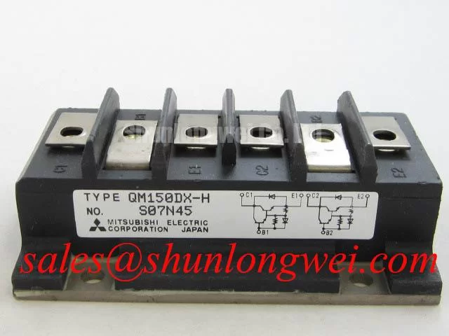
The QM150HY-H is a Mitsubishi Electric isolated Darlington module with an official rated voltage of 600 V and rated current of 150 A. These are the primary factory-listed identification points for evaluating a replacement in a heavy-duty variable-frequency AC motor drive. The module category, terminal arrangement, base-drive requirements, thermal interface, and switching behavior must be matched against the original equipment documentation before energization.
Desaturation protection must be treated as a system-level protection function rather than an assumed internal feature of the QM150HY-H. A Darlington module can be exposed to severe short-circuit energy when the base command remains active during a phase-to-phase fault, a motor-cable fault, or a failed commutation event. The protection circuit should therefore monitor the switching node through an appropriate sensing path and remove drive energy rapidly when the measured condition indicates abnormal conduction.
For a heavy-duty AC motor drive, the protection architecture may evaluate both a fast Type I response and a controlled Type II response. The first response is intended to interrupt an immediately destructive short circuit, while the second response can apply a controlled turn-off profile that reduces the voltage rise caused by stray inductance. A sub-10-microsecond target is a design consideration for the complete protection loop, not an official switching or short-circuit withstand rating for this module. The final response time depends on the sensor, comparator, isolation device, base driver, wiring, and switching current.
A two-stage soft turn-off arrangement can be evaluated when the measured fault current is high but the circuit still requires controlled voltage management. The driver first reduces the base drive, then completes turn-off through a defined discharge path. This approach can reduce the severity of inductive overshoot, but the correct sequence must be validated with an oscilloscope using the installed busbar, snubber, motor cable, and load. The module’s 600 V voltage rating should not be treated as permission to operate at an uncontrolled switching peak.
Keep the fault-sensing loop physically separate from high-current commutation paths where practical. Base-return conductors should follow the intended drive reference rather than sharing a long path with the power emitter or return conductor. Designers should minimize parasitic loop inductance, maintain suitable insulation clearance for the actual DC-link environment, and verify the peak terminal voltage during turn-off testing. Clearance and creepage are determined by working voltage, pollution level, altitude, insulation system, and applicable equipment standards; they are not fixed by the product name alone.
During field replacement, compare the module mounting position with the original busbar geometry before tightening any terminal. A misaligned copper bar can impose mechanical stress on the module terminal and alter the commutation path. Check that the base cable cannot move into the power-terminal field, and confirm that the protection circuit remains active when the controller is placed in service mode. For a drive that uses external desaturation protection, the sensing threshold and blanking behavior belong to the drive design and should be verified against the known-good phase leg.
For broader switching-layout guidance, engineers can consult the Power Electronics Masterclass, which addresses power-loop construction, transient control, and reliability evaluation across power semiconductor assemblies.
QM150HY-H Circuit Protection & Reliability: Calibrating Dynamic Power Loss Dissipation and Multi-R
Thermal evaluation begins with the actual pulse profile rather than the headline current value. The official 150 A rating identifies the module class, but junction temperature is influenced by conduction duration, switching frequency, duty cycle, case temperature, mounting quality, and the thermal path into the heatsink. In a pulsed overload, the case may remain relatively cool while the semiconductor junction experiences a rapid temperature excursion.
A multi-RC thermal model is useful when the drive repeatedly applies short overload pulses. The model represents the junction-to-case response as several thermal sections with different time constants. A practical engineering calculation combines the measured or documented power pulse with the transient thermal impedance curve, then compares the predicted junction temperature with the applicable device limit from the original technical documentation. The resulting margin is system-specific and should not be inferred from the 600 V and 150 A catalogue values alone.
Measure the heatsink interface after the module has been removed from service. Look for uneven contact, excessive compound displacement, surface contamination, or a distorted mounting plane. The thermal path is affected by the entire assembly, including the module base, interface material, heatsink, airflow, and enclosure temperature. A replacement module installed on a compromised surface can show abnormal thermal behavior even when the electrical connections are correct.
Parallel operation requires particular care. The positive temperature coefficient of conduction voltage can support static current sharing in some bipolar power-device arrangements, but it does not remove the need for symmetrical busbars, equal electrical path lengths, matched base-drive conditions, and balanced thermal coupling. Each parallel module must experience a comparable impedance path during both conduction and commutation. Verify current balance under the intended load instead of assuming that physical proximity guarantees equal sharing.
Where the drive includes a controlled rectifier or an auxiliary front-end stage, the system engineer may evaluate the related QM300DY-2H as a separate topology element. That comparison should remain electrical and mechanical: voltage class, current path, control method, mounting pattern, thermal interface, and protection coordination must all be checked independently. A related part is not an automatic substitute for the QM150HY-H.
Power-factor correction and phase-controlled rectifier behavior can also affect the stress seen by the motor-drive DC link. Firing-angle changes alter conduction intervals and input current harmonics, while a weak or heavily distorted supply can increase ripple-related heating. The appropriate harmonic filter, line reactor, or active front-end strategy is determined by the complete drive topology and installation standard. The module itself should not be presented as an independent EMC-certified assembly.
QM150HY-H Operational Boundaries: Evaluating High dv/dt Cross-Conduction Shoot-Through Limits
Cross-conduction risk increases when a high-voltage switching transition couples through base-collector capacitance, common inductance, or an inadequately controlled return path. The QM150HY-H product information supplied for this page confirms its 600 V rated voltage and isolated Darlington construction, but it does not establish a built-in active clamp or a specific negative base bias requirement. Those functions belong to the selected base driver and protection architecture unless the original module documentation states otherwise.
A dedicated low-impedance clamp or controlled base-drive path may be evaluated when the measured switching transition produces unintended base movement. The clamp or drive-control circuit should be placed according to the driver manufacturer’s layout guidance and connected with the shortest practical control path. The correct clamp current, trigger level, and turn-off behavior must be established from the base-emitter waveform at the module terminals, not from a controller-side test point.
Negative base bias is not established here as a QM150HY-H factory requirement. Applying a negative voltage without checking the module’s base-emitter limits can create a different failure mechanism. Designers should use the original base-drive specification and confirm positive and negative base-emitter excursions during normal switching, fault turn-off, startup, and shutdown.
Dead-time prevents the upper and lower devices in a bridge leg from receiving overlapping commands, but the required interval depends on propagation delay, driver mismatch, turn-off behavior, stored charge, temperature, and load current. A controller setting copied from another module may be unsuitable. Check both base-emitter waveforms and the phase-node transition, then adjust the control sequence only after confirming that the power stage remains within its voltage and current boundaries.
Long motor cables introduce transmission-line effects. Reflected waves can raise the motor-terminal voltage and return stress to the inverter during fast transitions. Cable length, characteristic impedance, motor insulation, switching edge rate, output filter design, and grounding arrangement determine the final waveform. When a drive is connected to a long cable, inspect the phase-to-phase and phase-to-ground waveforms at the inverter and motor ends. An output reactor or dv/dt filter may be appropriate, but its selection is a system-engineering decision.
Control algorithms also influence current tracking and switching activity. The deadbeat control algorithm is one example of a control approach used for fast inverter current tracking; its sampling, prediction, and command timing must be assessed together with base-driver delay and the module’s actual switching response. The Mitsubishi Electric power semiconductor reference material provides wider context for switching-device technology, but it should not be read as a QM150HY-H-specific operating guarantee.
Benchtop Waveform Tuning: Mitigating Stress via Cold-State Main Terminal Impedance on QM150HY-H
Cold-state screening should be completed with the drive isolated, the DC link discharged, and all external control connections removed where the equipment procedure permits. Use a digital multimeter in diode-check mode across the main terminals and record the polarity, displayed forward threshold, and open-circuit behavior. Compare the readings with a known-good module or the original service baseline rather than assigning a universal pass or fail voltage to every installation.
Repeat the check in the reverse direction and inspect for unexpected low impedance between main terminals. A reading that differs materially from the reference unit may indicate a damaged semiconductor path, an attached snubber, a connected motor cable, or another parallel circuit. Isolate external branches before interpreting the result. The measurement is a screening method, not a substitute for a controlled powered test.
If the assembly includes an antiparallel diode or another auxiliary conduction path, identify that path from the original circuit documentation before using diode mode. Do not assume that every isolated Darlington module has the same internal arrangement or terminal order. Confirm the terminal markings, base reference, and power polarity from the equipment drawing and the module documentation.
Base-emitter leakage should be checked with an instrument and test voltage appropriate to the documented base limits. Keep the base-emitter path controlled during the measurement so that static charge does not create a misleading reading. A suspected leakage condition should be compared with the reference module under the same test setup, with the result recorded before any base resistor, driver board, or snubber is reconnected.
After the cold checks, reconnect the drive in stages. First confirm the isolation and base-drive reference, then verify command polarity and interlock behavior without applying the full DC link. During the first powered test, use current limiting and observe the base-emitter waveform, phase-node transition, DC-link ripple, and case temperature. Any unexpected overshoot or asymmetric phase behavior calls for a controlled shutdown and inspection of the complete commutation loop.
Field Alert: Disconnect power and wait for the DC link to discharge before removing cables, and apply the fastener and thermal-interface procedure specified by the equipment documentation.
For replacement evaluation, the official product identity remains Mitsubishi Electric QM150HY-H, 600 V, 150 A, isolated Darlington module. The QM120DX-H may be reviewed as a separate same-family comparison, but voltage, current, mechanical fit, drive compatibility, and protection behavior must be checked before any substitution decision.