Content last revised on September 15, 2026
SKD82/08 Thermal-Electrical Optimization: High-di/dt Commutation and Practical Thermal Tuning
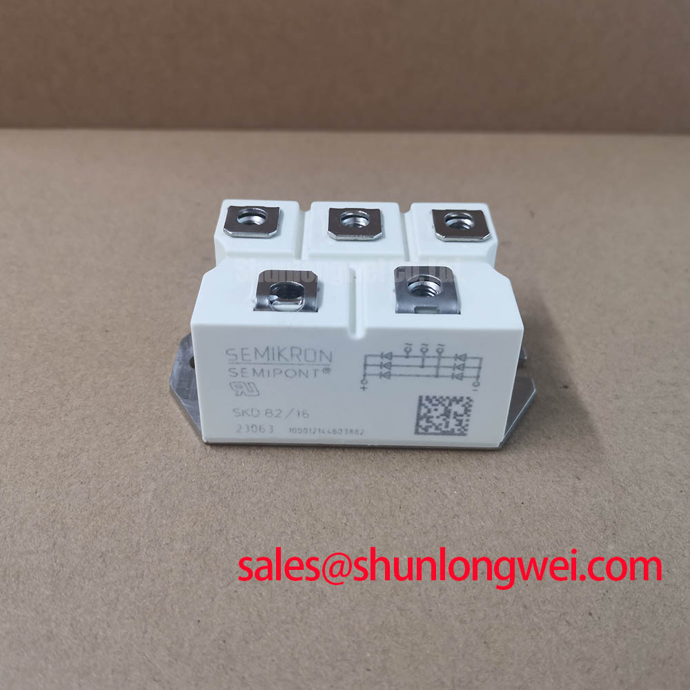
Start a cold inspection by isolating the power stage, checking the module body for cracking, and verifying the marked terminals against the original bridge wiring before applying any test voltage. The Semikron SKD82/08 is a SEMIPONT 2 bridge rectifier module with an official 800 V reverse recurring peak voltage rating and an official 82 A mean forward current at Tc = 85°C. It is suitable for evaluation in industrial rectification stages where mechanical fit, thermal transfer, surge coordination, and isolation must be confirmed against the equipment design.
| Technical specification | Official rating | Engineering significance |
|---|---|---|
| Reverse recurring peak voltage | 800 V | Defines the repetitive reverse-voltage boundary for the rectifier bridge. |
| Mean forward current | 82 A at Tc = 85°C | States the continuous current capability under the specified case-temperature condition. |
| Surge forward current | 700 A at 10 ms, 25°C | Provides the specified short-duration surge reference for charging and inrush events. |
| Thermal resistance | 0.15 °C/W, total module | Describes the specified junction-to-case heat-transfer path for heatsink evaluation. |
| Isolation voltage | 2500 V AC | Supports insulation coordination between the module and a grounded cooler when the system design permits it. |
| Package | SEMIPONT 2 | Provides the mechanical and terminal arrangement used for installation assessment. |
The SKD82/08 should first be identified correctly in the circuit. Its stated product category is a bridge rectifier module, so it is not a gate-controlled thyristor and does not accept gate firing pulses, gate damping resistors, back-porch holding current, or multi-pulse trigger commands. In an SVC installation, the firing function belongs to the separately controlled thyristor-switched capacitor branch, while this module may be evaluated in an upstream or auxiliary rectification stage. The system integrator should verify the schematic position rather than applying thyristor gate-drive procedures to this diode bridge.
For a stopped cabinet, use the equipment drawing to identify each AC input and DC output path, then perform cold resistance and diode-mode checks with the module fully isolated from capacitors, contactors, and parallel semiconductor paths. A reading that differs from a known-good assembly may indicate a damaged junction, a parallel current path, or a wiring issue; confirm the result by lifting the relevant connection and comparing the complete signal and power path. The official 82 A at Tc = 85°C rating is not a free-air current promise. Cooling conditions, current waveform, enclosure temperature, and the actual mounting interface remain system-level conditions.
Fuse coordination must be completed from the applicable Semikron documentation and the selected semiconductor fuse data. The supplied product parameters do not include a fuse I²t coordination table, so a protection value should not be invented from the 700 A surge rating. Engineers should compare the fuse clearing characteristic, prospective fault current, repetitive charging duty, and the bridge’s specified surge conditions before approving the replacement. The Semikron-Danfoss Power Electronics & Modules Official Hub is an appropriate reference point for manufacturer documentation.
Transient Dynamics & Electrical Design: Diode Peak Reverse Recovery Current and Switching Behavior on SKD82/08
A bridge rectifier can experience commutation transients when its current transfers between AC phases, transformer windings, line reactors, or downstream capacitors. The supplied official data confirms the repetitive reverse-voltage rating of 800 V, but it does not provide reverse-recovery peak current, reverse-recovery time, softness factor, or switching-loss curves for this exact part. Those characteristics must therefore be verified from the applicable datasheet or laboratory waveform measurement rather than inferred from the current and voltage ratings.
During commissioning, monitor the voltage across the rectifier terminals and the current in the commutation loop under the actual transformer, line impedance, and DC-link conditions. Excessive ringing may involve wiring inductance, inadequate suppression, transformer leakage, control timing elsewhere in the system, or an unsuitable protection network. A practical design consideration is to minimize the high-current commutation loop and place approved suppression components according to the equipment insulation and service requirements. The final peak-voltage margin must be confirmed by the system engineer during switching tests against the module’s 800 V VRRM rating.
The SKD 25/14 can be reviewed as a neutral reference for a different Semikron rectifier position in a power topology. It should not be treated as an automatic substitute for the SKD82/08. Terminal configuration, current duty, voltage class, cooling arrangement, and the original equipment drawing must all agree before any cross-reference is considered.
Benchtop Waveform Tuning: Managing Thermal and Surge Stress on SKD82/08
For an isolated bench check, allow the DC link to discharge through the equipment’s approved discharge circuit, confirm zero energy with an appropriately rated meter, and disconnect external wiring before measuring the bridge. Inspect the mounting surface and the module body, then check that the heatsink contact is clean and flat enough for the specified installation method. The official total-module thermal resistance is 0.15 °C/W, but the installed thermal result also depends on the interface material, clamping method, heatsink, airflow, and ambient conditions.
The 700 A surge forward current at 10 ms and 25°C is a defined surge reference, not a continuous overload allowance and not a guarantee for repeated capacitor-charging cycles. When testing a capacitor-input supply or an SVC auxiliary converter, record the inrush waveform, repetition rate, pre-existing case temperature, and protective-device clearing behavior. Repeated surges should be evaluated against the complete thermal cycle and fuse coordination data. The supplied specifications do not establish avalanche energy, repetitive surge lifetime, FIT rate, or field failure probability, so those claims should not be assigned to this model without a traceable source.
⚠️ Field Alert: Follow the applicable Semikron mounting procedure and fastener torque specification, apply the approved thermal interface material evenly, and never reconnect the power terminals while the DC link or control supply remains energized.
Assembly Integrity & Layout Architecture: Bridge Rectifier Integration for SKD82/08
Firing-angle control from zero to 150 degrees belongs to a controlled thyristor converter, not to this passive bridge rectifier. The SKD82/08 conducts according to the polarity applied to its AC terminals and load path; it does not generate a selectable delay angle or directly regulate reactive power in a thyristor-switched capacitor branch. In a grid-tied SVC, designers should map this module’s exact position in the rectification, sensing, auxiliary supply, or protection section before assessing compatibility with the control topology.
Mechanical assembly should preserve the original terminal orientation, creepage arrangement, conductor support, and cooling path. Verify the 2500 V AC isolation voltage requirement against the complete installation, because module isolation alone does not establish system certification or cabinet-level insulation compliance. The SEMIPONT 2 package should be compared with the existing footprint, terminal spacing, heatsink interface, and enclosure clearances before installation.
For troubleshooting data, capture the AC-side voltage, rectified output, load current, case temperature, and control signals from the adjacent SVC switching section at the same operating point. If the replacement restores conduction but the capacitor bank still shows abnormal switching, inspect the separate thyristor trigger circuit, snubber network, contactor timing, and line reactor. The Precision Gate Drive Design resource may assist with the controlled semiconductor section, while the SKD82/08 itself should remain evaluated as the specified bridge rectifier.