

Content last revised on September 21, 2026
Assembly Integrity & Layout Architecture: Implementing DC-Bus Operating Voltage Headroom Derating for SKIIP26AC126V1
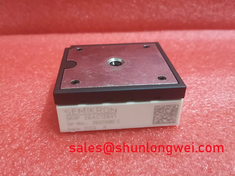
The 1200 V rating is the official blocking-voltage boundary of SKIIP26AC126V1, not a guaranteed operating DC-bus target. Before commissioning, the service engineer should verify the installed DC-link voltage, regenerative bus rise, brake-chopper function where fitted, and measured switching overshoot. This establishes whether actual operating peaks remain within the module’s documented electrical limits under the machine’s real acceleration and deceleration profile.
DC-bus headroom is a Design Consideration because it depends on the DC-link architecture, switching behavior, motor cable, protection response, and measured temperature. At elevated installation locations, designers may evaluate environmental effects such as reduced air density and the wider engineering discussion around terrestrial neutron exposure. No model-specific FIT rate, single-event burnout probability, altitude derating value, or service-life prediction is stated here because those values require applicable manufacturer data and system-level qualification evidence.
For repair work, inspect copper clearances, contamination paths, loose bus joints, damaged insulation barriers, and cracked solder at high-current joints. A conductive residue or loose DC-link connection can create irregular transient behavior that is not visible during a static diode check. Clearance and creepage requirements should be determined from the complete equipment voltage, pollution degree, enclosure, insulation system, and applicable safety standard rather than assigned from the module rating alone.
Semikron’s MiniSKiiP power module information provides useful product-family context when assessing package integration. Where the original assembly calls for another member of the same product family, SKIIP37AC12T4V1 can be reviewed as a separate reference item; mechanical fit, terminal assignment, drive interface, thermal behavior, and protection coordination must be confirmed from the equipment documentation before any substitution decision.
Transient Dynamics & Electrical Design: Turn-Off di/dt-Induced Vpeak Clamping on SKIIP26AC126V1
During turn-off, the voltage at the switching device can rise above the DC-link level because stray inductance stores energy while current changes. In engineering terms, the observed peak is governed by the DC-bus voltage plus the inductive contribution of stray loop inductance multiplied by current slew rate. This is an Engineering Calculation principle, but the actual result must be captured at the installed converter because probe method, layout, load current, gate network, and commutation path all influence the waveform.
For SKIIP26AC126V1 integration, minimize the physical area enclosed by the DC-link capacitor, bus conductors, and module power path to suppress turn-off overshoot. Symmetrical, low-inductance bus geometry and capacitors placed close to the switching loop are common Design Considerations. Snubber selection should not be copied from a different inverter rating or package. The system engineer should validate it using switching tests that measure peak voltage, ringing frequency, capacitor heating, and the energy returned to the DC link.
Switching frequency and cooling conditions also require system-level evaluation. The official 26 A current rating does not by itself establish usable current at every switching frequency, airflow condition, heatsink arrangement, or ambient temperature. When integrating into a high-dynamics multi-axis CNC or robotics servo drive, engineers should verify the application duty cycle and current waveform against the relevant Semikron documentation and the measured thermal condition of the installed assembly.
Long motor cables deserve separate attention during commissioning. Reflected-wave behavior at the motor end can increase cable-end voltage stress, while a noisy output waveform can also complicate sensor and encoder troubleshooting. Output filtering, cable selection, grounding arrangement, and motor insulation compatibility are Engineering Recommendations to be verified for the complete motion system. If the converter includes a separate input rectifier or auxiliary conversion stage, the role and ratings of associated devices such as SKM100GB063D should be reviewed independently rather than inferred from the rating of this module.
SKIIP26AC126V1 Operational Boundaries: Evaluating Galvanic Gate Drive Isolation, Reinforced Limits
The module’s official data provided here identifies its voltage rating, current rating, and MiniSKiiP / SKiiP package family. It does not establish a gate-driver isolation voltage, reinforced-insulation classification, or common-mode transient immunity value for the complete drive. Those properties belong to the chosen gate-drive system, isolation components, printed-circuit-board layout, cabling, and installed insulation barriers.
When a drive shows intermittent gate-related behavior, begin by checking the connector engagement, gate-drive supply stability, command signal reference, and controller fault records. Measure gate-emitter behavior with suitable isolated instrumentation and compare it to the known-good channel and the original design requirements. A distorted command waveform, unexpected ringing, or uneven drive response may indicate a layout, connector, driver, or supply issue; it should not be assigned to the power module without corroborating measurements.
Galvanic isolation is a Design Consideration that prevents the control domain from being directly referenced to hazardous power circuitry. The required barrier performance depends on the equipment’s safety architecture, DC-link voltage, installation category, insulation coordination, and governing product standard. Designers should verify that PCB creepage, clearance, connector insulation, and driver isolation are evaluated as one assembly. A module alone should not be described as independently certified for system EMC performance or for a specific reinforced-isolation category.
The gate loop should be kept physically compact and separated from high-current power paths where the equipment layout allows. This reduces coupling that can disturb switching commands during rapid voltage transitions. The proper damping arrangement, gate-drive polarity, and protection timing are system-determined and should be proven through controlled switching tests, especially after a repair involving DC-link capacitors, wiring, gate-driver boards, or motor cable replacement.
For broader application-level discussion of IGBT implementation and reliability considerations, see Industrial Applications. Semikron-Danfoss also describes the package-family approach in its SKiiP technology reference.
Field Diagnostics & Commissioning: Kelvin Emitter Connection in SKIIP26AC126V1 Topologies
Do not assume that every package variant exposes a separate Kelvin-emitter connection. The service engineer should verify the exact terminal assignment for SKIIP26AC126V1 from the original equipment schematic and applicable manufacturer documentation before probing or reconnecting the gate-driver interface. Connecting a gate reference to an incorrect terminal can produce misleading bench readings and may place the drive circuit outside its intended control reference.
Where the verified topology provides an auxiliary emitter reference, its purpose is generally to provide the gate driver with a quieter local return path than a shared high-current emitter route. This is a Design Consideration for reducing mutual coupling between the power loop and gate loop. The main power conductor must still carry load current according to the converter layout, while the gate-drive return should follow the documented control reference path.
Commissioning should proceed from static checks to controlled energization. Confirm that the DC-link capacitors are discharged before continuity work, inspect the motor phases for unintended shorts to the chassis, and verify that all control connectors are fully seated. During first power application, monitor the DC bus, protection status, and gate-drive behavior using equipment-rated test methods. If a fault recurs only under load, capture phase current and switching-node behavior against a known-good channel or approved waveform reference.
A repeated overcurrent or desaturation trip can result from several conditions, including motor-cable damage, phase-to-phase load imbalance, a failed gate-drive channel, poor cooling contact, a DC-link problem, or an actual switching-device fault. Isolate each path methodically. Record the fault condition, operating state, bus voltage, commanded axis motion, and measured waveform evidence so that the repair decision is based on the converter’s observed behavior rather than a single static measurement.