
Content last revised on September 27, 2026
SKIIP83AHB08T2 Current Sharing and Derating
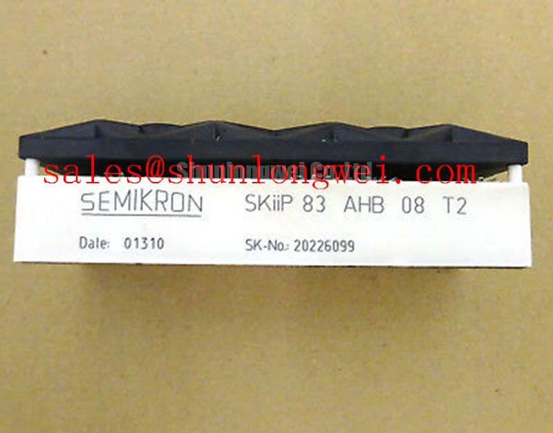
When evaluating SKIIP83AHB08T2 for a heavy-duty variable frequency AC motor drive, compare its voltage and current ratings with the drive’s measured operating conditions. As a Design Consideration, derating should account for DC-link variation, switching transients, cooling performance and repetitive load cycles. The system designer should establish the permissible margins from the applicable module documentation and tests in the actual drive.
If the circuit places switching devices in parallel, static and dynamic current sharing need separate checks. A positive temperature coefficient of collector-emitter saturation voltage can assist static sharing under suitable operating conditions, but that behavior should not be assumed for this specific module without its characteristic curves. Gate-path impedance, conductor symmetry and thermal contact also influence balance. During diagnosis, compare switching waveforms and temperatures across equivalent paths before attributing uneven loading to the module.
Keep gate-drive routing distinct from high-current paths where the documented terminal arrangement permits it. Do not assume that an auxiliary emitter terminal exists: verify every connection against the original pinout. Similarly, inspect conductor spacing at the module interface and adjoining board, then assess creepage and clearance against the complete assembly’s voltage, contamination and insulation requirements rather than treating a package-family name as an insulation rating. Semikron-Danfoss describes the broader MiniSKiiP power-module family; family information does not replace this model’s documentation.
SKIIP83AHB08T2 Fault Detection and Turn-Off Behavior
A desaturation indication calls for waveform review, not an immediate diagnosis of a failed module. On a suitable drive, inspect the sense circuit, gate supply, current path and controller fault record, then compare the event with a known-good switching path if available. Type-I and Type-II short-circuit events impose different stresses; detection delay and clearing behavior must be checked against the documented safe-operating limits of the fitted device and the drive’s measured response. No short-circuit withstand time is established by the supplied 800 V and 83 A ratings alone.
As a Design Consideration, a controlled turn-off strategy can reduce the inductive voltage rise during fault clearing, but its implementation and timing belong to the drive design. Minimize the commutation-loop area and place any specified snubber connection close to the switching path; verify the result through measured collector-emitter voltage during representative switching and fault tests. A film snubber, DC-link capacitor bank and any MOV serve different transient-control roles. Their coordination must be assessed from the drive schematic and measured waveforms rather than inferred from the module part number.
Unexpected fault trips may also reflect common-mode disturbance reaching an optocoupler or digital isolator. Review the isolator’s specified common-mode transient immunity against the measured drive environment, and inspect gate-return routing before changing detection thresholds. Precision Gate Drive Design provides further context for that board-level review.
Thermal Interface and Mounting Checks for SKIIP83AHB08T2
Before installation, examine the mating surfaces for debris, damage and uneven contact. Apply thermal-interface material according to the applicable module and heatsink instructions, aiming for continuous contact without relying on a thick layer to compensate for a poor mounting surface. The supplied product parameters do not establish a grease thickness, baseplate curvature or screw torque for SKIIP83AHB08T2; obtain those requirements from the relevant mechanical documentation.
After assembly, check that the module seats evenly and that the heatsink, cooling flow and temperature measurement points match the drive design. If a repaired drive develops a temperature imbalance, inspect mounting contact and cooling conditions alongside electrical loading. The Semikron-Danfoss SKiiP technology information offers package-family context, while the original mounting instructions remain the authority for this installation.
DC-Link Layout and Replacement Fit
At turn-off, voltage across the switching device includes the DC-link voltage and a contribution from loop inductance as current changes. As a Design Consideration, keep the capacitor-to-module current path compact and balanced to limit that overshoot, then measure the peak against the documented device limit under the drive’s relevant conditions. Capacitor selection also requires the drive’s ripple-current, voltage and thermal requirements; the module rating alone cannot size the bank.
Pro Tip: Preserve balanced DC-bus routing during a repair and confirm turn-off voltage with a switching measurement before returning the drive to service. If a replacement is being evaluated, SKIIP37AC12T4V1 is a separate Semikron model to compare, not an assumed drop-in equivalent. Check its documented circuit arrangement, terminal map, mechanical fit, gate-drive requirements and thermal behavior against the original drive before making a substitution decision.