Content last revised on April 26, 2026
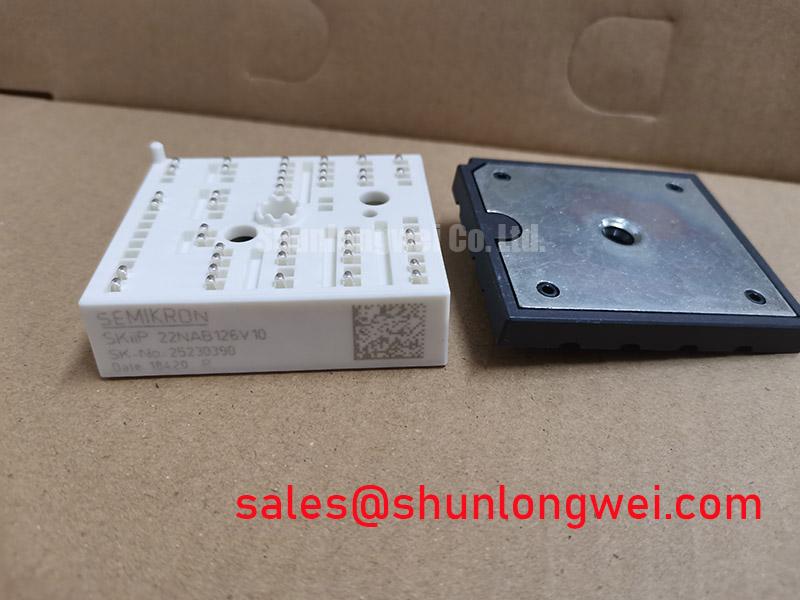
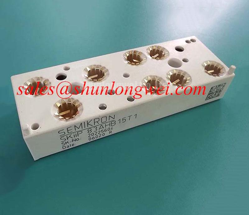
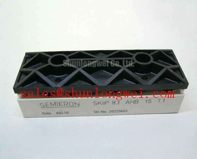
SKIIP83AHB15T1: Integrated Power Module Engineered for Superior Drive Reliability
A Technical Overview of the SEMIKRON 3-Phase Rectifier and Brake Chopper Module
The SEMIKRON SKIIP83AHB15T1 redefines drive reliability through its advanced pressure contact technology, delivering superior thermal cycling performance and simplified integration for compact motor control systems. This intelligent power module integrates a 3-phase rectifier and a braking chopper featuring core specifications of 1200V (IGBT) | 95A (Ic @ 25°C) | Rth(j-h) 0.35 K/W. Its key engineering benefits include enhanced operational lifetime and streamlined assembly. By leveraging a solder-free design, it directly addresses the common failure mechanism of solder fatigue, making it an optimal choice for dynamic, start-stop motor control applications. For systems prioritizing robust performance and high power density in demanding industrial environments, this module offers a distinct advantage.
Application Scenarios & Value
System-Level Benefits in Compact Motion Control Systems
The SKIIP83AHB15T1 is engineered for designers of compact AC motor drives and servo systems where both reliability and space are critical constraints. Its high level of integration, combining the AC-to-DC rectification stage and a dynamic braking chopper into one housing, is fundamental to achieving a smaller system footprint. This integration significantly simplifies the DC bus layout and reduces the number of required electrical connections, which in turn minimizes potential points of failure and shortens assembly time.
Consider a material handling application, such as an automated conveyor or a robotic arm, that experiences frequent acceleration and deceleration cycles. These operations cause significant temperature swings within the power electronics. The SKIIP83AHB15T1's core value is its use of SKiiP® pressure contact technology. Unlike conventional soldered modules, this design eliminates solder layers, which are often the primary wear-out mechanism under thermal stress. This results in superior Power Cycling Capability, extending the operational lifetime of the entire Variable Frequency Drive (VFD). The integrated temperature sensor further empowers the system controller to actively manage thermal performance, ensuring the drive operates within its specified Safe Operating Area (SOA) even under peak loads. For less demanding applications or where a different braking strategy is employed, the related SKIIP83ANB15T5 offers a similar topology with an uncontrolled rectifier.
Key Parameter Overview
Decoding the Specs for Enhanced Thermal Reliability
The specifications of the SKIIP83AHB15T1 are tailored for robust performance in industrial power conversion. The following table highlights the key metrics that directly influence its application suitability and design integration.
| Parameter | Symbol | Value | Conditions |
|---|---|---|---|
| Collector-Emitter Voltage (Chopper) | Vces | 1200 V | - |
| Continuous Collector Current (Chopper) | Ic | 95 A / 65 A | Th = 25°C / 80°C |
| Collector-Emitter Saturation Voltage | VCE(sat) | 2.5 V (typ) | Ic = 75 A, Tj = 25°C |
| Repetitive Peak Reverse Voltage (Rectifier) | VRRM | 1500 V | - |
| Thermal Resistance, Junction-Heatsink (IGBT) | Rth(j-h) | 0.35 K/W | Per IGBT |
| Total Switching Energy | Eon + Eoff | 18 mJ (typ) | Ic = 75 A, Tj = 125°C |
Technical Deep Dive
A Closer Look at Pressure Contact Technology for Long-Term Reliability
The defining feature of the SKIIP83AHB15T1 module is its reliance on pressure contact technology, a design philosophy that directly confronts a primary cause of power module failure: solder fatigue. In a traditional module, the silicon die is soldered to a Direct Copper Bonded (DCB) substrate, which is then soldered to a copper baseplate. Each of these layers has a different coefficient of thermal expansion (CTE). As the module heats and cools during operation, mechanical stress builds at these solder interfaces, eventually causing cracks and leading to thermal failure.
What is the primary benefit of its pressure-contact design? Enhanced long-term reliability by eliminating solder fatigue. The SKiiP design replaces these critical solder joints with a precisely engineered pressure system. The module is mounted with two screws, applying uniform force that ensures a stable, low-resistance connection between the internal components and the external heatsink. Think of it like a high-performance engine head gasket; it relies on consistent pressure to maintain a perfect seal, rather than a rigid, brittle adhesive. This approach dramatically improves the module's resilience to the repetitive thermal stresses inherent in motor drive applications, leading to a quantifiable increase in operational lifetime and a lower total cost of ownership. For a broader understanding of how IGBT technology has evolved, see this in-depth analysis of IGBT modules.
Frequently Asked Questions (FAQ)
How does the pressure contact system in the SKIIP83AHB15T1 simplify the manufacturing process?
The pressure contact design simplifies assembly by removing the need for complex and carefully controlled soldering processes. Mounting is achieved with two main screws, which is faster and more repeatable than reflow soldering an entire module. This reduces manufacturing complexity, lowers the risk of solder-related defects, and can increase throughput on the assembly line.
What is the engineering advantage of integrating a temperature sensor directly into the module?
The integrated NTC temperature sensor provides a real-time, accurate measurement of the substrate temperature, close to the semiconductor junctions. This allows the drive's control system to implement precise over-temperature protection, preventing catastrophic failures. It also enables advanced thermal management strategies, such as derating power output gracefully when approaching thermal limits, thereby maximizing system uptime without compromising safety.
For what type of applications is an integrated rectifier and brake chopper module most suitable?
This integrated topology is ideal for AC motor drives in the 15-30 kW range that require dynamic braking to dissipate regenerative energy. Common applications include elevators, cranes, conveyors, and robotics, where rapid deceleration or stopping of high-inertia loads is necessary. Integrating these functions reduces system size, cost, and complexity compared to using discrete components.
How does the 0.35 K/W Rth(j-h) value impact heatsink selection?
The thermal resistance from junction to heatsink (Rth(j-h)) is a critical parameter for thermal design. A lower value, like the 0.35 K/W specified for the IGBT in this module, indicates more efficient heat transfer from the silicon die to the heatsink. For an engineer, this means that for a given power loss, the junction temperature will be lower. This provides two options: use a smaller, less expensive heatsink for the same performance, or push for higher power output while staying within the maximum junction temperature limits, thus increasing the system's power density. Explore more on why this matters in our guide to unlocking IGBT thermal performance.
Strategic Application
For engineering teams developing next-generation motor drives and power converters, the SKIIP83AHB15T1 offers a strategic path toward higher reliability and power density. The shift to solder-free pressure contact technology is not merely an incremental improvement but a fundamental enhancement of the module's resilience against common wear-out mechanisms. By specifying this module, designers can build systems with longer service intervals and greater robustness, aligning with industry demands for lower maintenance and higher availability in critical applications from industrial automation to renewable energy systems.