
Content last revised on October 30, 2026
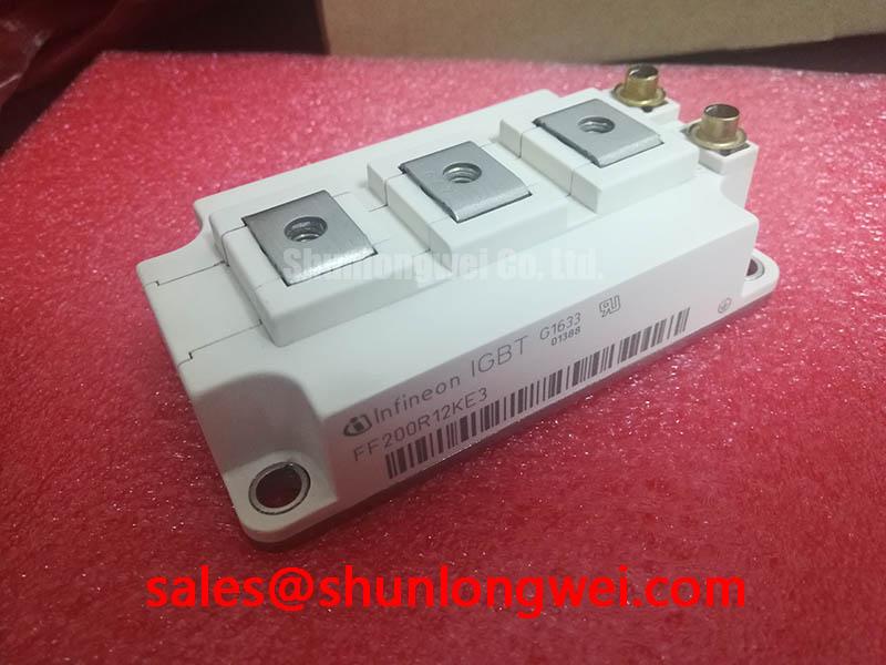
SKM200GAH123DKL Operational Boundaries: Evaluating Derating Guidelines and Parameter Limits
I first compare the collector, emitter, and gate identification against the circuit drawing, then record cold-state measurements with the module isolated from the driver. Diode-mode readings should follow the documented internal circuit and probe polarity; connected snubbers or parallel devices can otherwise obscure the result. A handheld meter does not establish collector-emitter blocking capability or operating-current performance.
Official Specification: the Semikron SKM200GAH123DKL IGBT module has a collector-emitter voltage rating of 1200 V. Its continuous collector current is 200 A at Tc = 25°C and 150 A at Tc = 80°C. Typical collector-emitter saturation voltage is 1.70 V at Ic = 150 A and Tj = 25°C. These conditions matter when comparing measurements: a cold diode-mode reading is not a saturation-voltage test.
Design Consideration: parallel-operation assessment should use the temperature-dependent output curves. Where those curves show a positive saturation-voltage temperature coefficient at the intended operating current, warmer devices can shed some steady-state current. This does not establish dynamic sharing. Symmetrical gate paths, comparable power-loop impedance, and matched thermal interfaces remain separate checks.
For replacement evaluation, compare SKM200GAL123D by circuit configuration, terminal mapping, mechanical fit, and driver requirements—not by the similar designation alone. Package dimensions, mounting details, insulation test conditions, and auxiliary-terminal assignments require the model-specific datasheet.
Benchtop Waveform Tuning: Evaluating the Gate Return Connection on SKM200GAH123DKL
Trace the driver return to its actual emitter connection before interpreting gate ringing. Design Consideration: an auxiliary emitter return, where explicitly identified in the terminal drawing, lets the gate circuit avoid part of the voltage developed across the high-current emitter path.
Route an identified auxiliary return with the gate conductor rather than through the load-current busbar. Observe gate-emitter voltage at the relevant module terminals using suitable differential measurement equipment; a remote controller-ground reference can conceal local ground bounce. If negative turn-off bias is being evaluated, its magnitude and switching excursions must remain within the documented gate limits and the driver's operating envelope.
Assess creepage along insulating surfaces separately from clearance through air. Working voltage, transient environment, contamination, and the applicable equipment standard determine the required distances. The collector-emitter rating does not establish terminal-to-baseplate insulation performance. Busbar alignment should avoid terminal strain, with fastening and vibration retention following the approved assembly instructions.
💡 Bench Tip: Discharge the DC link and apply ESD controls before cold-state probing, then compare readings with a known-good module under the same meter polarity and temperature.
Transient Dynamics & Electrical Design: Balancing Switching Dissipation vs di/dt on SKM200GAH123DKL
Separate turn-on and turn-off behavior when checking an existing driver board. Official Specification: typical turn-on energy is 17.5 mJ and turn-off energy is 21 mJ, both at Vcc = 600 V and Ic = 150 A. These are operating-point values, not fixed losses across every gate resistance, junction temperature, or switching frequency.
Design Consideration: external turn-on resistance affects current rise and commutation behavior; turn-off resistance influences voltage overshoot and switching dissipation. Where the driver provides separate paths, evaluate them independently while observing collector-emitter voltage, collector current, and local gate-emitter voltage. Select the eventual settings from measured stress and thermal performance rather than copying the previous module's resistor values.
Keep gate routing away from high-slew-rate power conductors and minimize shared return impedance. Check measurement-loop pickup before attributing every oscillation to the semiconductor. Manufacturer resources at the Semikron-Danfoss Power Electronics & Modules Official Hub provide the appropriate context for device documentation and application guidance.
SKM200GAH123DKL Circuit Protection & Reliability: Calibrating Thermal Stress Alleviation in Bidirectional Converters
Evaluate heating through power reversals rather than checking only the highest steady load. For compatibility assessment in commercial string inverters and micro-grid energy storage, designers should map conduction and switching duty across charging, discharging, and reactive-power operation. Four-quadrant behavior belongs to the converter topology and control strategy, not to an individual module designation.
Official Specification: IGBT junction-to-case thermal resistance is 0.12 K/W. Design Consideration: transient temperature assessment also needs the applicable thermal-impedance characteristics, interface performance, and cooling boundary conditions. The Semikron Sintering Technology resource explains a packaging approach; it does not establish that this model uses that construction. Broader converter context is available in Industrial Applications.
Coordinate desaturation detection, blanking, and soft shutdown with switching measurements and the documented short-circuit safe operating area. Normal saturation voltage is not a standalone fault threshold. Protection validation should check both rejection of ordinary switching transients and controlled interruption of fault current without excessive collector-emitter overshoot.