Content last revised on October 8, 2026
Assembly Integrity & Layout Architecture: Implementing Thermal Cycling Margins of Internal Braking for SKM300GAL123D
| Manufacturer | Semikron |
|---|---|
| Product Category | IGBT Module |
| Rated Voltage | 1200 V |
| Rated Current | 300 A |
| Package | Semitrans |
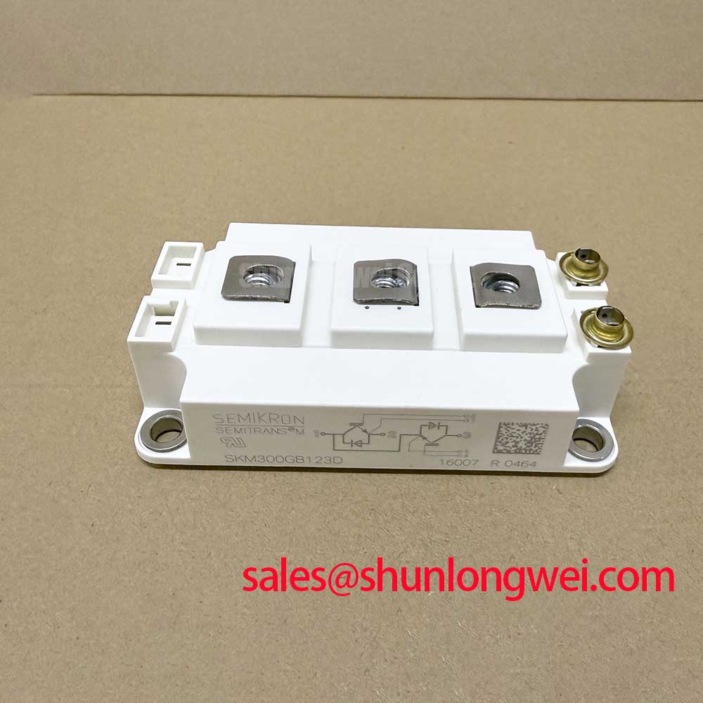
Measure the brake circuit for phase to phase shorts, inspect the module mounting interface, and compare the cold resistance readings with a known good assembly before energizing the traction inverter. The SKM300GAL123D is identified by the supplied manufacturer data as a Semikron 300 A, 1200 V IGBT module in a Semitrans package. Those ratings establish the component identity and electrical boundary; they do not by themselves define the permissible braking pulse, switching frequency, or heat-sink temperature.
For an electric forklift or warehouse vehicle drive, an internal or external braking branch must absorb regenerative energy when motor deceleration raises the DC link. The ballast resistor, switching device, DC-link capacitor, fuse, and cooling assembly should be evaluated as one energy path. Designers should calculate the deceleration energy from the motor and vehicle operating conditions, then verify the resistor pulse rating and the module junction temperature during the complete braking cycle. A resistor that survives a short bench pulse can still impose excessive thermal cycling during repeated loading.
Keep the high-current commutation loop compact and physically separated from gate-control wiring. The positive and negative power paths should follow the intended circuit topology with low parasitic inductance, while the gate return should not share a noisy power-current route. Confirm the collector, emitter, and gate terminal identity from the original Semikron documentation and the equipment schematic rather than relying on connector position alone. The Semikron-Danfoss SEMITRANS industry information provides useful family-level context, but the application design remains system dependent.
During incoming inspection, use a diode-test measurement only after isolating the module from capacitors, gate drivers, snubbers, and parallel semiconductor paths. Record the polarity and relative forward-voltage behavior of each accessible antiparallel diode path, then repeat the measurement with the probes reversed. A low impedance in both directions, an unexpected open circuit, or a reading that differs substantially from parallel positions warrants isolation testing and schematic review rather than an immediate failure declaration.
Parallel devices require particular attention to copper symmetry, gate-loop symmetry, and thermal contact. Positive temperature coefficient behavior can support static current sharing, but dynamic sharing still depends on gate resistance, stray inductance, driver timing, and the physical layout. When comparing a lower-current family member such as SKM75GAL063D, treat it as a separate electrical option, not an automatic substitute for the 300 A module.
SKM300GAL123D Operational Boundaries: Evaluating High-Speed Fault Management: VCE Desaturation Limits
Probe the gate command, emitter reference, collector voltage, and desaturation response with isolated measurement equipment while the inverter is operated under a controlled low-energy condition. The supplied product data confirms the voltage and current ratings, but it does not provide an official short-circuit withstand time, desaturation threshold, type-I or type-II short-circuit specification, or a guaranteed sub-microsecond protection interval for this device.
Desaturation protection is normally a system-level method for detecting an abnormal rise in collector-emitter voltage while the gate command remains active. Its useful response depends on the driver circuit, blanking interval, diode network, wiring inductance, measurement reference, and the fault current rise rate. A protection designer may use a staged turn-off strategy, reducing the gate drive more gently at the first detection event and completing turn-off under a separately verified gate-current limit. This is an engineering recommendation for the driver, not an official SKM300GAL123D parameter.
Capture the turn-off waveform at the module terminals, not only at the driver board. The observed collector-emitter overshoot includes the effects of busbar inductance, capacitor placement, probe loop area, and commutation current. Minimize the power-loop inductance to suppress inductive overshoot, then verify the measured peak against the DC-link operating voltage and the module’s 1200 V rating during switching tests. An RC or RCD snubber, active clamp, or revised gate network may be considered only after the measured transient and switching loss are understood.
Fast semiconductor fuses should be coordinated with the equipment fault-clearing strategy and the module’s documented short-circuit and surge data. The fuse I2t value cannot be selected from the 300 A continuous rating alone because cable inductance, DC-link capacitance, prospective fault current, and clearing time influence the stress. If a dead-short event has occurred, inspect the module, fuse, gate driver, bus capacitors, and current sensor together before returning the traction stage to service.
For gate-drive work, the Precision Gate Drive Design resource can serve as a system-level reference for layout, timing, and protection review. 💡 Bench Tip: use an ESD-controlled bench and record cold-state readings before connecting the module to any powered gate driver.
Assembly Integrity & Layout Architecture: Checking Insulation Barrier Integrity for SKM300GAL123D
Check insulation resistance between the isolated power terminals, the mounting surface, and the heat sink with the module disconnected from all control and auxiliary circuits. Do not assign a reinforced insulation voltage or common-mode transient immunity value to the SKM300GAL123D unless that value appears in the applicable device documentation and matches the installed assembly.
Isolation performance is determined by the module construction, thermal interface, mounting hardware, contamination level, creepage and clearance in the surrounding assembly, and the test method. The supplied parameters identify a Semitrans package but do not state a guaranteed isolation rating above 5 kV or a CMTI value above 100 kV/µs. Those figures must not be used as assumed design limits.
Route isolated gate-drive signals so that high dv/dt collector nodes do not run parallel to sensitive control traces for unnecessary distances. Keep the gate return referenced to the correct emitter point, avoid unintentional chassis-current paths, and inspect the heat-sink interface for conductive debris or damaged insulating material. If a driver reports intermittent gate triggering, compare the command waveform with the gate-emitter waveform directly at the module terminals while observing the collector transition with a properly rated differential probe.
Repeated thermal cycling can alter interface pressure, compound distribution, and mechanical contact. Check the mounting surface for flatness and contamination, apply the thermal interface material according to its supplier process, and tighten the assembly using the module and heat-sink manufacturer’s documented procedure. A sound insulation test at room temperature does not replace verification at the expected thermal and electrical operating conditions.
Transient Dynamics & Electrical Design: Assessing Reliability in High-Altitude Operation for SKM300GAL123D
Measure the actual DC-link voltage, switching overshoot, and fault waveform at the installation altitude before attempting any reliability calculation. The SKM300GAL123D supplied data establishes a 1200 V rated voltage and 300 A rated current, but it does not provide FIT data, single-event burnout probability, neutron-flux sensitivity, altitude derating, or a guaranteed operating lifetime.
Terrestrial neutron exposure can be relevant to high-voltage power semiconductors, especially where repetitive switching and high electric-field stress coincide. A valid SEB or FIT assessment requires an authoritative device-specific test method, exposure data, DC-link conditions, temperature profile, mission duration, and failure definition. Without those inputs, assigning a numerical FIT rate or claiming a fixed altitude limit would be technically unsupported.
For equipment deployed above approximately 2000 m, treat reduced cooling performance, insulation coordination, and atmospheric conditions as separate design considerations. Recalculate the heat-removal path using the enclosure, fan, heat sink, and ambient conditions of the vehicle or charger. Verify switching peaks against the module’s voltage rating under worst-case regeneration, line disturbance, and braking events rather than applying an assumed percentage derating.
When a field module fails after a high-energy transient, preserve the gate-driver waveform, fuse condition, DC-link capacitor condition, and event log before replacing parts. Check whether the failure occurred during turn-on, turn-off, braking, or a short-circuit response, then compare the captured voltage and current traces with a controlled reference test. The official Semikron-Danfoss power electronics hub provides manufacturer-level product context, while the final voltage margin, protection timing, and thermal validation must be established for the complete traction system.