Content last revised on September 10, 2026
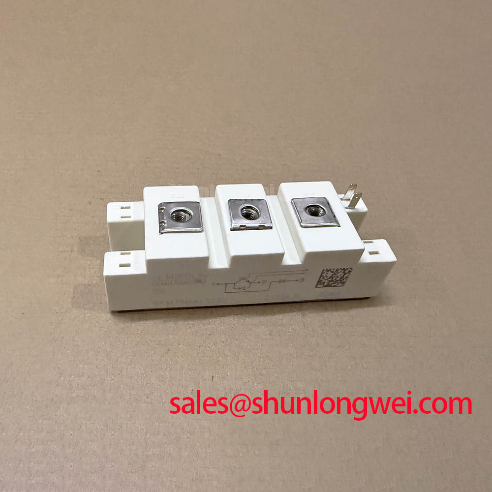
Semikron SKM75GB12F4 High-Speed 1200V Half-Bridge IGBT Module
The Semikron SKM75GB12F4 delivers ultra-low switching losses in high-frequency power conversion systems operating above 15 kHz. Rated at 1200V and 75A with an insulated copper DBC baseplate, it solves severe thermal accumulation challenges in compact converter designs.
Top Specs: 1200V | 75A | Rth(j-c) 0.325 K/W.
- Ultra-Fast Switching: Minimal tail current for frequencies exceeding 15 kHz.
- CAL4 Soft Recovery: Dramatically curtailed reverse-recovery oscillations and EMI noise.
Does the module maintain safe switching margins under high di/dt? Yes, its CAL4 freewheeling diode suppresses voltage spikes during rapid turn-off transients.
Application Scenarios & Value
Achieving System-Level Efficiency in High-Frequency Power Stages
For resonant inverters prioritizing high switching rates above 15 kHz, this 1200V 75A module is the optimal choice.
Engineers often face severe thermal bottlenecks when driving hard-switched converters at frequencies exceeding 15 kHz. Standard 1200V silicon IGBTs typically suffer from pronounced tail currents during turn-off, which generate intense switching dissipation and force thermal down-rating.
The SKM75GB12F4 addresses this trade-off by combining high-speed trench/field-stop IGBT4 dies with ultra-fast CAL4 freewheeling diodes in an industry-standard SEMITRANS 2 package. Think of its high-speed field-stop structure like a high-performance camera shutter that snaps shut instantly, preventing energy leakage during every switching cycle.
In high-frequency industrial power systems such as switched-mode power supplies (SMPS), un-interruptible power supplies (UPS systems), and electronic welding units, reducing dynamic losses translates directly into smaller filter inductors and reduced heatsink volume. Engineers designing high-frequency induction generators can explore specialized conversion techniques detailed in high-frequency induction heating topologies.
For systems that demand higher output current capabilities in the same high-speed class, the related SKM400GB12F4 provides a 400A rating, while standard motor drive applications running under 8 kHz often utilize the robust SKM75GB128D.
Technical & Design Deep Dive
Loss Minimization and Thermal Dynamics Across the Half-Bridge
The internal architecture of the Semikron SKM75GB12F4 integrates an insulated Direct Bonded Copper (DBC) substrate that offers an AC isolation voltage rating of 4000V. The junction-to-case thermal resistance (Rth(j-c)) is strictly specified at 0.325 K/W per IGBT switch and 0.60 K/W for the freewheeling diode.
Under heavy switching conditions (600V bus, 75A collector current at Tj = 150°C), turn-on energy dissipation (Eon) is measured at 6.8 mJ, and turn-off energy dissipation (Eoff) remains at just 5.3 mJ. This low combined loss is made possible by an optimized gate charge (QG = 425 nC) and a rapid fall time (tf = 61 ns). To understand how internal charge dynamics govern these transitions, review our guide on IGBT switching principles.
The companion Semikron CAL Diode acts like an automotive hydraulic damper during commutation: it softly absorbs reverse recovery current without generating snappy voltage spikes, safeguarding the complementary high-side switch against dv/dt induced shoot-through.
Key Parameter Overview
Essential Engineering Specifications for Circuit Assessment
The following technical parameters highlight the primary electrical and thermal ratings extracted from the official datasheet:
| Parameter / Symbol | Condition / Test Level | Datasheet Value | Engineering Significance |
|---|---|---|---|
| Collector-Emitter Voltage (VCES) | Tvj = 25°C | 1200 V | Provides safe operating margin for 400V–480V AC rectified DC buses. |
| Continuous Collector Current (IC) | Tc = 80°C (Tj = 175°C) | 72 A (Nominal: 75 A) | Defines continuous load carrying capacity under practical thermal design constraints. |
| Saturation Voltage (VCE(sat)) | IC = 75A, VGE = 15V, Tj = 150°C | 2.60 V (typ) / 2.93 V (max) | Establishes conduction power dissipation during on-state operation. |
| Turn-On Switching Loss (Eon) | VCC = 600V, IC = 75A, Tj = 150°C | 6.8 mJ | Key factor in calculating dynamic heatsink loading above 15 kHz. |
| Turn-Off Switching Loss (Eoff) | VCC = 600V, IC = 75A, Tj = 150°C | 5.3 mJ | Minimized tail current ensures elevated efficiency in high-frequency stages. |
| Thermal Resistance (Rth(j-c)) | Per IGBT switch | 0.325 K/W | Dictates thermal transfer efficiency from semiconductor die to copper baseplate. |
| Insulation Voltage (Visol) | AC sinus 50 Hz, 1 min | 4000 V | Ensures galvanic safety compliance in high-power industrial equipment. |
Frequently Asked Questions
Engineering Clarifications on Thermal and Gate Drive Integration
What is the primary benefit of the F4 high-speed silicon technology in the SKM75GB12F4?
What is the primary benefit of its high-speed trench design? Drastically lower dynamic switching losses at frequencies above 15 kHz.
How does the CAL4 diode improve circuit reliability during rapid commutation?
How does the CAL4 diode improve circuit reliability? Soft-recovery characteristics suppress voltage spikes and minimize electromagnetic interference.
How does the Rth(j-c) of 0.325 K/W impact thermal budget planning?
The low thermal resistance allows higher continuous switching power dissipation while maintaining the junction temperature well within the recommended 150°C operational limit.
What gate driver voltage levels are recommended for driving this module?
Semikron recommends a forward drive voltage of +15V to achieve the specified VCE(sat) and a negative bias of -8V to -15V to prevent parasitic turn-on in high di/dt half-bridge converters.
Can the SKM75GB12F4 be integrated into standard SEMITRANS 2 mechanical footprints?
Yes, it utilizes the standard 94 mm x 34 mm DBC module layout, ensuring mechanical compatibility across industrial converter platforms.
Strategic hardware implementations rely on accurate thermal modeling and balanced gate resistance to exploit the full frequency capability of the Semikron SKM75GB12F4 in advanced power electronic designs.