Content last revised on October 11, 2026
SW16CXC14C Inspection and Replacement Considerations
Isolate the power stack, verify that stored energy has discharged, and disconnect parallel current paths before checking the SW16CXC14C with a multimeter. Compare the forward and reverse responses with an equivalent serviceable position using the same instrument settings; an in-circuit reading can include snubbers and adjacent devices rather than the capsule alone.
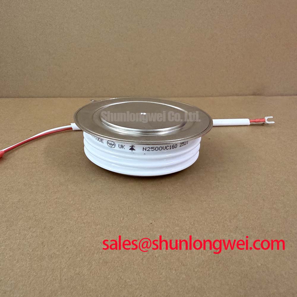
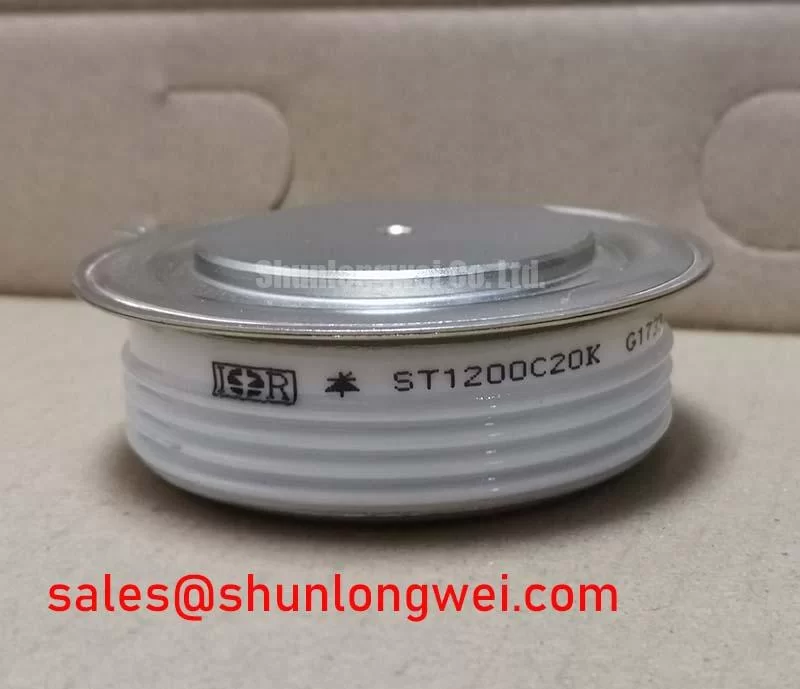
The Westcode SW16CXC14C is a discrete power diode with a specified 1600 V voltage rating, 3270 A current rating, and Disc Capsule / Press-Pack package—Official Specifications. For replacement assessment, consult the manufacturer datasheet for the rating definitions and test conditions, recovery characteristics, surge capability, fuse coordination, capsule dimensions, polarity, and clamping requirements. These details establish compatibility beyond the headline electrical ratings.
Preventing Spurious Faults: AC-to-DC Transfer Characteristics for SW16CXC14C Applications
Trace the bridge schematic before interpreting a low DC-output alarm: the SW16CXC14C is a diode, so it does not receive a firing-angle command. As a Design Consideration, firing-angle analysis belongs to the controlled devices elsewhere in a mixed or fully controlled converter, not to this diode’s terminal characteristics. Distinguish an input rectifier position from a freewheeling or commutation position before comparing operating waveforms.
For a converter whose approved control procedure examines firing angles from zero to 150 degrees, compare measured DC output with the expected transfer characteristic for that exact topology. Source impedance, current continuity, and commutation overlap influence the result. In a conventional phase-controlled rectifier, delayed firing generally reduces average rectified output and changes displacement power factor; reactive demand also depends on loading and conduction mode. Treat this as system behavior, not a specified operating range for the SW16CXC14C.
A useful commissioning record pairs supply voltage and current waveforms with DC output and the controller’s firing reference. Unequal phase currents or missing conduction intervals warrant checking the supply, connections, and controlled-device triggering before assigning the fault to a diode. Harmonic distortion and displacement power factor should be evaluated separately rather than inferred from one current reading.
When assessing a medium-frequency induction melting or hardening furnace rectifier, engineers should verify the original stack configuration, cooling arrangement, and protection schedule. The related SW18CXC22C can be included in a documented comparison, but its model designation does not establish interchangeability. Compare polarity, mechanical interfaces, current-rating conditions, recovery behavior, and surge coordination before considering a substitution.
Field Diagnostics & Commissioning: Reverse-Recovery Current in SW16CXC14C Topologies
Capture diode current and terminal voltage through commutation to distinguish reverse-recovery behavior from probe artifacts and circuit ringing. As an Engineering Recommendation, use appropriately rated isolated measurement equipment and establish probe polarity, bandwidth, and timing alignment before interpreting the reverse-current peak.
Reverse recovery occurs when stored charge is removed as conduction changes direction. Peak reverse-recovery current and recovery duration depend on the preceding forward current, junction temperature, and imposed current slope. Recovery softness describes the shape of the current’s return toward its blocking state; it is not interchangeable with recovery time. Comparing traces is meaningful only when their operating conditions are comparable.
As a Design Consideration, minimize unnecessary commutation-loop inductance to limit voltage excursions, then validate the resulting waveform against the circuit’s operating boundaries. Snubber changes should follow measured behavior and the equipment design rather than a generic component-value prescription. A multimeter cannot establish dynamic recovery performance, and a ringing trace alone does not establish a defective capsule.
For broader technology comparisons, Wide Bandgap Revolution discusses GaN and SiC integration considerations. That background does not establish the SW16CXC14C’s semiconductor material, recovery specifications, or replacement compatibility. Likewise, switching-waveform measurements support equipment-level interference assessment; they do not constitute EMC certification of this diode.
Assembly Integrity & Layout: Applying ITSM Safety Derating to Repetitive Fault Conditions for SW16CXC14C
Match the protective fuse’s let-through energy and clearing behavior to the diode’s surge limits before returning the stack to service. As a Design Consideration, a sinusoidal 10 ms half-cycle is a surge-test waveform, not permission for repetitive overload. Its applicability depends on the manufacturer’s stated initial temperature, waveform, and reverse-voltage reapplication conditions.
Evaluate repetitive disturbances using the actual load sequence and cooling recovery between events. A non-repetitive surge rating cannot serve as a repetitive current allowance. Fuse coordination should account for both energy let-through and peak current at the prospective fault level, with the equipment engineer checking the complete protection sequence.
Inspect the capsule seating faces, cooling contacts, and clamp alignment against the assembly drawing. For a press-pack assembly, fastener torque is not a direct substitute for verified axial clamping force; spring-stack condition and the specified loading procedure matter. Field Alert: Apply the approved stack clamping procedure rather than estimating capsule pressure from bolt tightness.
The general mechanism described in thermal fatigue explains why repeated temperature changes deserve attention, but that reference is not a product-specific power-cycling standard or evidence of internal bond-wire construction. After reassembly, verify cooling performance, connection voltage drops, and temperature trends under the equipment’s approved commissioning sequence before releasing the repaired stack.