Content last revised on October 14, 2026
High-Humidity Storage Margins (60°C / 90% RH) & Delamination Prevention Protocols
Place the display in its intended mechanical frame before humidity evaluation, then inspect the viewing area under uniform white, black, red, green, and blue screens. This reveals edge haze, localized luminance changes, and perimeter defects that may not appear during a brief electrical start-up. The TCG084VGLAAANN-AN51 is identified here as a Kyocera TFT-LCD Active Matrix Color Display Module; the supplied product data does not establish a manufacturer-rated humidity endurance profile, optical contrast value, coating specification, or thermal-cycle guarantee.
For a high-humidity storage assessment, use the original enclosure, gasket arrangement, cable routing, and mounting pressure rather than testing the bare panel alone. A 60°C and 90% RH exposure can be treated as a Design Consideration for a system-level evaluation, not as an official rating for this model. After conditioning, allow the assembly to return gradually to room conditions before applying power. Check for perimeter clouding, visible separation near the glass edge, connector-area corrosion, and changes in uniformity across the active image.
Sub-zero evaluation requires particular care because liquid-crystal viscosity can increase as temperature falls, producing slower gray-to-gray transitions, temporary smearing, or grayscale nonuniformity. These observations should be recorded as temperature-dependent behavior rather than assigned to a specific internal failure mechanism. A thermal sequence spanning approximately −30°C to +85°C may be used only when required by the equipment qualification plan. The system engineer should correlate image response, start-up behavior, and seal integrity after each temperature dwell.
Direct sunlight testing should separate panel readability from camera exposure effects. If the equipment specification calls for contrast above 500:1 at 50,000 lux, treat that value as a system acceptance target unless it appears in the original Kyocera documentation for this exact ordering code. Anti-glare performance should be judged with the final cover window and viewing angle installed. Kyocera’s industrial TFT-LCD display technology resources provide useful background for evaluating optical integration without assigning unverified construction details to this display.
Micro-Twist Mechanical Stress Fracture Prevention on Glass Substrate Driver Bumps
Run the panel through full-field red, green, blue, white, and black images before applying any mechanical adjustment, then repeat the sequence after installation. A uniform-color screen makes isolated pixel defects easier to classify, while a black screen exposes light leakage and uneven backlight behavior. Use a flashlight at approximately 45 degrees to cast a controlled shadow across the surface; a shadow that moves with the external illumination is more likely to involve the optical stack, while a fixed line or localized image interruption requires closer examination of the panel and signal path.
Do not twist the glass while aligning the bezel or cable. The correct procedure is to support the panel across its designed mounting surfaces, seat the frame without point loading, and confirm that the connector remains parallel to the mating socket. 💡 Bench Tip: Wear ESD protection and lock the flexible cable only after its exposed contacts are fully parallel and evenly inserted.
For high-EMI equipment, differential routing should preserve the original signal topology and avoid unnecessary stubs. A 100 Ω ± 10% differential target and skew of no more than 50 ps may be used as Design Considerations for a compatible high-speed interface, but they are not official electrical ratings supplied for the TCG084VGLAAANN-AN51 in the stated product data. The engineer should compare the actual controller interface, cable construction, termination method, and oscilloscope waveform against the known-good assembly.
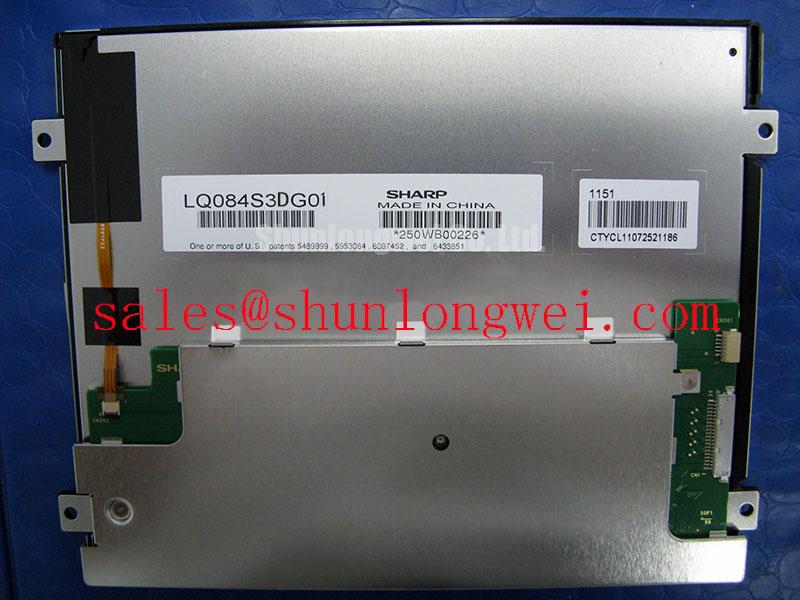
When a replacement is being considered, compare active area, connector position, mounting envelope, optical direction, controller timing, and backlight requirements rather than relying on diagonal size alone. The linked LQ070Y3LW01 can be included in a neutral replacement study, but compatibility must be demonstrated through mechanical and electrical comparison before procurement approval.
Solid-State WLED Constant-Current Driving, 1000:1 PWM Dimming & Flicker Suppression
Identify the installed backlight architecture before applying a driver or changing the brightness-control signal. The supplied baseline describes this product as a TFT-LCD Active Matrix Color Display Module, but it does not confirm a WLED backlight, CCFL ignition requirement, constant-current input, PWM ratio, half-life, or acoustic behavior. Those properties must therefore remain system-integration checks rather than product claims.
If the original medical display uses a CCFL subsystem, a cold-ignition assessment in the 1500 to 1650 Vrms range belongs to the external inverter and lamp assembly, not automatically to the LCD panel. If the equipment uses solid-state LED illumination, verify the driver’s current regulation, enable sequence, dimming polarity, minimum pulse behavior, and fault response against the original display electronics. A stated 1000:1 PWM dimming objective may be used as a system-level engineering target when required by the controller specification; it should not be presented as an official feature of this ordering code without supporting documentation.
Flicker evaluation should combine a photodetector measurement with visual inspection at several brightness settings. Check whether the modulation originates in the LED driver, the display controller, or the camera interaction used by the diagnostic equipment. Audible buzz should be traced to the external power and backlight assembly rather than attributed to the panel without evidence. For an auxiliary display power topology, engineers may review the LQ10D41 as a separate supporting device, while keeping its electrical role distinct from the Kyocera display itself.
Where the finished surgical navigation or ultrasound terminal must remain readable under strong ambient illumination, evaluate the complete optical stack, including cover glass, diffuser arrangement, surface treatment, and backlight uniformity. A contrast target above 500:1 at 50,000 lux and a 50,000-hour half-life requirement are application specifications only unless the original panel documentation explicitly assigns them to this model. Optical references concerning diffusers and brightness-enhancement films can help structure the test, but they do not verify the construction of this Kyocera unit.
Dynamic Contrast Ratio Stabilization & Liquid Crystal Birefringence Temperature Tracking
Measure grayscale steps at the actual operating temperature and viewing direction instead of judging contrast from a single front-facing image. Liquid-crystal birefringence changes with temperature, and the resulting tonal shift can influence shadow detail, highlight separation, and apparent viewing-angle performance. The TCG084VGLAAANN-AN51 product data supplied here does not identify the panel mode as TN, IPS, or MVA, nor does it confirm a symmetric 85°/85°/85°/85° viewing specification.
For a medical display evaluation, place the panel at the intended operator position and record grayscale visibility while moving through the required horizontal and vertical angles. If grayscale inversion appears, compare it with the controller’s gamma tables, source bit depth, and timing configuration before attributing it to the liquid-crystal cell. T-CON timing, gray-level reference voltages, and gamma correction should be adjusted only through the original controller design or an approved replacement board; the display listing does not establish those circuit values.
Dynamic contrast testing should use repeatable image content rather than automatic camera exposure. Record black-level lift, white-field uniformity, and transition behavior at cold, room, and warm conditions. If the finished unit requires a full symmetric viewing cone of 85°/85°/85°/85°, treat that as a project acceptance criterion requiring measurement. It is not an official rating confirmed for this part in the supplied baseline.
High-EMI installations should preserve controlled differential routing where the controller interface requires it. A 100 Ω ± 10% differential impedance objective and skew no greater than 50 ps are suitable Design Considerations for interface validation, subject to the actual controller and cable specification. Engineers evaluating long-term HMI integration can also consult the Industrial Display & HMI Solutions resource for broader enclosure, optical, and environmental test planning.