Content last revised on October 30, 2026
Tianma TM057KDH01-41 Display Inspection and Integration
- Disconnect the display cable with equipment power isolated, then inspect connector seating, cable strain, and exposed contacts before bench testing.
- Match the TM057KDH01-41 identification to the equipment bill of materials and confirm the controller supports its CMOS interface.
- Inspect the bezel gasket for displaced edges and uneven compression; check that mounting hardware does not load the viewing surface.
- Allow a cold display assembly to acclimatize in a dry environment before applying power if condensation is present.
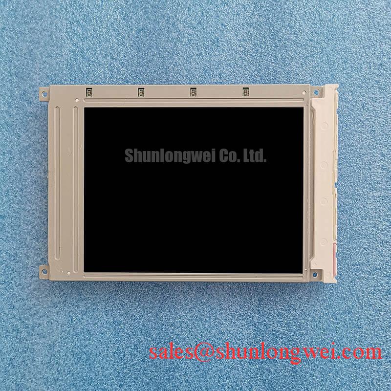
The Tianma TM057KDH01-41 is a 5.7-inch, 640 × 480 LCD display with a CMOS, single-channel, 6-bit interface. Its VGA image format is relevant when evaluating a replacement for a precision electronic test and measurement instrument whose controller, enclosure, and software require this display configuration.
| Technical metric | Official Specification | Integration significance |
|---|---|---|
| Screen size | 5.7-inch diagonal | Check the complete mechanical drawing, not diagonal size alone. |
| Resolution | 640 × 480 pixels | Native VGA image with a 4:3 aspect ratio. |
| Luminance | 400 cd/m² | Assess readability through the installed cover window. |
| Interface | CMOS, 1 channel, 6-bit; 33 pins | Match pin assignments and controller timing before connection. |
| Color capability | 262K colors | Match the host output format. |
| Contrast ratio | 500:1 | Evaluate dark and light interface elements under installed lighting. |
| Operating temperature | −20°C to +70°C | Applies to operation, not an assumed storage qualification. |
| Active area | 115.2 × 86.4 mm | Defines the image area, not the outside mounting envelope. |
| Additional integration limits | Consult Datasheet | Supply voltage, timing, storage humidity, outline dimensions, and fastening requirements. |
High-Humidity Storage Margins (60°C / 90% RH) & Delamination Prevention Protocols
Inspect the display perimeter and cover-window interface for trapped moisture, lifted edges, or irregular optical patches before accepting an assembly from humid storage. Design Consideration: the temperature and humidity combination in this heading is an environmental assessment condition, not an established TM057KDH01-41 storage rating. The specified operating range does not establish resistance to condensation or prolonged damp storage.
When transferring equipment between cold and warm areas, keep the assembly unpowered until surface moisture has cleared. Examine gasket continuity and enclosure drainage without applying pressure to the panel edge. Optical bonding is an enclosure-level integration choice: adhesive compatibility, moisture exposure, and mechanical stress require validation for the completed assembly. Bonding alone does not establish a hermetic seal.
Cold liquid crystal response can become slower, making transitions appear smeared or delayed. Evaluate moving grayscale patterns alongside static images at the intended operating temperature rather than interpreting delayed updates as a controller failure. Operation below −20°C falls outside the stated range; neither colder operation nor extended thermal cycling is established by that rating.
The CMOS interface also changes the electrical review: differential-pair routing prescriptions are not a substitute for checking this panel’s parallel signal connections. Designers should assess clock integrity, signal return paths, and cable routing against the controller timing requirements. For manufacturer portfolio context, refer to Tianma Japan Industrial Display Portfolio; product-family information does not replace model-specific qualification limits.
Aluminum Heat Spreader Sizing & Thermal Interface Placement along Narrow Display Edges
Map temperature around the installed display edges and rear enclosure before choosing a heat-spreading rail. Design Consideration: an aluminum rail is an enclosure option, not a specified TM057KDH01-41 accessory. Its contact area and attachment should follow measured hot spots and available chassis paths, without transferring clamping pressure into the optical stack.
Compare temperature distribution with brightness uniformity after the enclosure reaches stable operating conditions. A localized bright or dark region can involve mechanical loading, illumination distribution, or other optical effects; temperature alone does not identify the cause. Keep thermal interface materials away from connectors and unsupported panel surfaces, and evaluate their compression through the enclosure assembly drawing.
The 400 cd/m² luminance specification is not a backlight lifetime statement. It does not establish an L70/B50 rating or identify the internal light-guide material. Manufacturer background on display technologies is available through Tianma Microelectronics Industrial TFT Displays, while endurance claims require supporting model-specific test conditions.
Review the controller, panel supply, and illumination circuit as separate parts of the display chain. The TX26D60VC1CAB is a separate display product for broader architecture comparisons, not an established peripheral backlight driver for this panel. At low temperature, characterize image response before considering enclosure heating; any heater control belongs to the system design and must avoid localized overheating.
Incoming Benchtop Inspection: COG/TAB Anisotropic Conductive Film (ACF) Integrity
Display full-screen red, green, and blue patterns, then inspect grayscale transitions and a dark field using the same controller configuration. Engineering Recommendation: record persistent lines, missing image regions, flicker, and illumination differences before changing cables or settings. These observations support fault isolation but do not establish a particular internal bonding construction or prove an ACF defect.
If the screen appears dark, illuminate it obliquely and look for a faint changing image while commanding known content. Visible image content can help separate an illumination-path problem from a complete loss of displayed data, but the result should be checked alongside power and signal measurements. Avoid pressing the panel edge to provoke intermittent faults.
Capture supply enable, controller output, and illumination enable during startup and shutdown. Compare their order with the panel and controller timing requirements. White screens and shutdown remnants can involve sequencing, interrupted data, or supply behavior; distinguish them by measurement rather than assigning a single cause. Change one condition at a time and retain the original waveform record.
For persistent static interface content, designers should consider screen blanking or changing idle content where the equipment permits, then evaluate image retention under representative use. Broader inspection practices are discussed in Industrial Display & HMI Solutions. Viewing-angle color changes should likewise be assessed at the installed operator position without assuming an IPS or MVA construction.
Industrial Bezel Mechanical Envelope Tolerances & Mounting Screw Torque Optimization
Check the bezel aperture against the 115.2 × 86.4 mm active area, then inspect clearance around the complete panel outline. The active area cannot determine mounting-hole positions, outer dimensions, or permissible edge compression. Design Consideration: gasket contact should remain continuous without concentrating force on a corner or obscuring the image.
Seat the assembly evenly and observe a dark field as the enclosure is secured using its approved fastening procedure. Changes in light leakage or cloudy patches during assembly warrant checking support flatness, gasket displacement, and cable interference. Fastener size and tightening torque belong to the actual chassis joint; a generic screw-torque value is not a panel mounting specification.
Maintenance Note: Periodically inspect enclosure airflow paths and gasket seating, with power isolated before disturbing the display connection.
During replacement evaluation, compare the LQ065T9DZ03A only through its own electrical and mechanical requirements; it is not established here as a direct replacement. Confirm connector mapping, timing, supply requirements, enclosure fit, and viewing characteristics before approving any different model. After reassembly, repeat dark-field and moving-image checks at the installed viewing position to identify pressure-related artifacts or response changes introduced by the enclosure.