Content last revised on October 16, 2026
Tianma TM101JDHG38 Display Identification and Integration
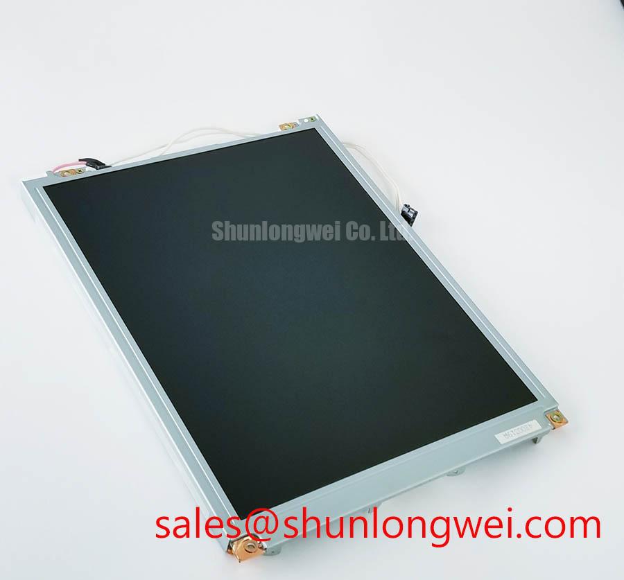
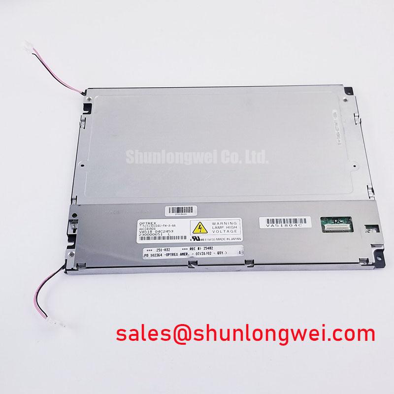
The TM101JDHG38 is a Tianma LCD display module identified as a TFT LCD active matrix color display module. Industrial display integration and replacement assessment require the original panel documentation and equipment drawings. The information available here does not establish a display voltage, interface pinout, luminance value, touch technology, backlight architecture, or operating temperature range.
- Manufacturer: Tianma
- Model: TM101JDHG38
- Product category: LCD display module
- Display construction: TFT LCD active matrix color display module
- Form factor: Confirm dimensions and mounting details from the module drawing
- Application assessment: Industrial HMI, protection equipment, and SCADA console integration require verification against host system requirements
When reviewing the panel for a high-voltage substation protection or dispatch console, the equipment engineer should match the mechanical opening, display cable, control electronics, touch assembly if fitted, and backlight driver as separate interfaces. The Tianma product information portal provides useful background on Tianma industrial TFT LCD display technologies, while the exact equipment replacement decision remains dependent on the host system documentation.
Flashlight Dark-Shadow Optical Diagnostic to Isolate Logic vs. Backlight Failure Modes
Start with a known operating state and display a white, red, green, and blue test sequence. A stable image that becomes visible under angled flashlight illumination while the panel appears dark points the investigation toward the illumination path, its driver, or its power control rather than immediately proving a panel logic failure. If no image is visible under the same test, the result is inconclusive; investigate the host controller, cable seating, panel timing, and display driver path alongside the illumination system.
For field work, keep the three primary color checks consistent between the suspected unit and a known-good assembly. Look for fixed vertical lines, horizontal bands, partial image regions, or localized areas that remain unchanged while the test color changes. Such patterns can be associated with signal integrity problems, connector contact issues, or damage in the panel driver region. The flashlight method is a screening technique, not a replacement for observing the panel interface with the equipment’s approved diagnostic procedure.
LED backlight aging should be discussed separately from the TM101JDHG38 identity. A stated value such as 50,000 hours to 50 percent brightness is not an official rating established by the information available here and must not be entered into a maintenance calculation as though it were. If a constant current driver is present in the host assembly, maintenance personnel can trend startup current, brightness uniformity, and driver fault indications over time. Open circuit and short circuit protection behavior belongs to the driver design, so its alarm output and restart sequence should be checked at the system level.
Maintenance Note: Inspect the cabinet airflow path and the display sealing gasket during scheduled service because blocked ventilation or a displaced gasket can accelerate optical and electrical stress.
Mitigating Gray-to-Gray Response Time Escalation during Cold-Start Machine Power-Up
Cold startup testing should concentrate on the time required for moving gray images, menus, and alarm graphics to settle after the console powers up. Liquid crystal viscosity generally increases as temperature falls, which can make gray-to-gray transitions appear slower even when the video source and panel logic are functioning correctly. This is a design consideration for any industrial LCD assembly and is not a declared response-time specification for the TM101JDHG38.
Record the visual response during a controlled thermal sequence while monitoring the host supply, display enable timing, and image source status. Compare static text, a moving status bar, and intermediate gray patterns rather than relying only on a full white screen. If the image becomes stable after warmup, investigate the enclosure thermal profile, condensation control, and the host startup sequence before changing the panel.
The perimeter seal should remain evenly supported when the module is installed in a metal bezel. Uneven compression can create visible edge shading or mechanical stress that changes as the enclosure warms. A heater strip must not be treated as a standard accessory for this model; where the host system uses one, its control strategy, insulation, and condensation protection should be evaluated by the system designer. Establish test temperatures from the documented module limits and host system requirements.
For maintenance teams, distinguish cold optical settling from a permanent line defect. A repeatable line in the same screen location across temperature changes deserves cable, connector, and panel driver investigation. A general delay that improves as the enclosure reaches operating temperature calls for thermal and power sequencing review.
Optical Luminance Degradation Curve and CCFL to LED Modernization Retrofit Pathways
Backlight modernization must begin by identifying what the existing equipment actually supplies to the display. The information available here does not establish whether the TM101JDHG38 uses CCFL or LED illumination, and it does not provide a guaranteed brightness half-life, PWM dimming range, ignition voltage, differential interface specification, or acoustic performance limit. Those values should therefore not be assigned to this model as product features.
For a legacy CCFL assembly, the service engineer should document the inverter connection, ignition behavior, audible noise, and high-voltage isolation procedure. For a conversion from CCFL to LED illumination, verify the replacement light source’s mechanical and optical compatibility, then match its driver to the actual LED configuration and verify current regulation, fault reporting, dimming control, and thermal behavior. A 1,500 to 1,650 Vrms cold ignition figure applies only when supported by the original CCFL system documentation. Similarly, a 1,000 to 1 PWM dimming ratio or a 50,000 hour half-brightness claim requires a specific driver or panel source.
| Evaluation item | TM101JDHG38 information | Replacement assessment requirement |
|---|---|---|
| Display type | TFT LCD active matrix color display module | Match optical stack, controller compatibility, and mechanical envelope |
| Form factor | Confirm from the module drawing | Confirm bezel opening, fixing points, cable exit, and rear clearance |
| Backlight | Not established by the information available here | Identify the original lamp or LED driver before retrofit planning |
| Alternative assessment | No equivalent established here | Evaluate TX18D210VM0BAA against the host panel documentation |
High EMI cabinet wiring also requires disciplined routing. If the host uses a differential display link, keep its pair arrangement continuous through the connector transition and validate common-mode noise, pair balance, and timing with the approved interface specification. Values such as 100 ohms differential impedance and 50 picoseconds skew should only be used when the selected interface documentation requires them; they are not established TM101JDHG38 parameters here.
Thermal Expansion Clearance Sizing across Heavy Industrial Metal Enclosure Cutouts
Mechanical installation should allow the display assembly to sit evenly in the enclosure opening without forcing the bezel, glass, or rear housing against a distorted cutout. Check the opening diagonally, inspect the gasket contact pattern, and tighten fasteners in a cross pattern so the load is distributed evenly. This helps reduce local pressure that can appear as edge shading, dark-field mura, or changing optical uniformity.
The information available here does not specify outer bezel dimensions, mounting-hole geometry, fastener torque, contrast ratio, sunlight performance, or anti-glare coating. The enclosure designer should establish the fastening method and torque from the applicable mechanical documentation and validate the installed panel under cold, warm, and direct-light conditions within its documented limits.
When the display is evaluated for a substation protection interface or SCADA dispatch console, check the gasket continuity after a thermal cycle, confirm that the metal cutout does not touch the active display area, and inspect the screen at normal viewing angles and under strong ambient light. Anti-glare or anti-reflection treatment should be confirmed from the actual panel build rather than assumed from the product category.
For broader installation and environmental test planning, the Industrial Display & HMI Solutions reference provides a useful framework for enclosure, optical, and service considerations.