

Content last revised on September 19, 2026
TT60F08KBC Thermal-Electrical Optimization: Surge Energy Dissipation and Clamping Voltage Practical Tuning
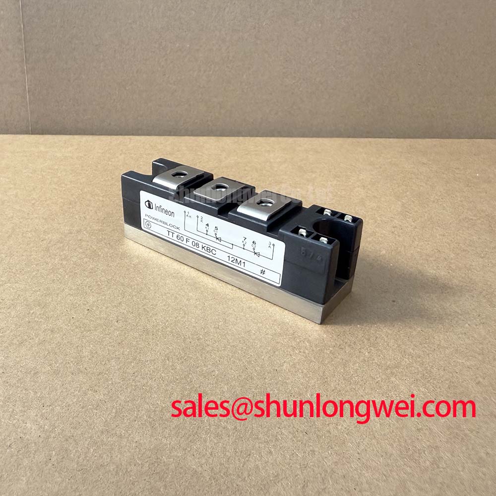
Before connecting a replacement module, isolate the equipment, read the housing marking, and confirm that the intended circuit position is compatible with the TT60F08KBC electrical boundary. This Infineon dual thyristor module has an official repetitive peak off state voltage rating of 800 V, an average on state current of 60 A at Tc = 85 C, a 1200 A at 60 Hz surge on state current rating, and a 2500 V AC isolation voltage rating.
| Official Specification | Value | Integration Relevance |
|---|---|---|
| Repetitive peak off state voltage, VDRM | 800 V | Voltage boundary for the thyristor blocking state |
| Average on state current, IT(AV) | 60 A at Tc = 85 C | Thermal operating reference for continuous current assessment |
| Surge on state current, ITSM | 1200 A at 60 Hz | Reference for nonrepetitive inrush and fault coordination |
| Fusing current, I2t | 7200 A2s | Reference point for semiconductor fuse coordination |
| Isolation voltage, Visol | 2500 V AC | Isolation boundary for heatsink mounting evaluation |
For a rectifier exposed to industrial AC disturbances, MOV and RC snubber selection is a Design Consideration, not an official TT60F08KBC setting. The protection network should limit transient stress at the module terminals while the system engineer verifies peak voltage under representative switching and surge conditions. The 800 V VDRM value is the specified repetitive blocking-voltage limit to check against those measurements.
Inspect busbar contact faces, terminal hardware, and heatsink flatness before applying power. A thin, continuous thermal interface layer is a general assembly practice intended to avoid local thermal discontinuities, while the required hardware torque must be verified from the module drawing and the equipment service documentation.
Bench Tip: De energize the assembly and discharge its DC link before moving meter probes or disconnecting any module terminal.
Assembly Integrity & Layout Architecture: Implementing Interphase Transformer Current Balancing for TT60F08KBC
In six pulse or twelve pulse rectifier assemblies, begin with the actual bridge schematic and identify each TT60F08KBC anode, cathode, and gate connection from the approved module documentation. A diode test can be useful for comparing cold state junction paths among corresponding modules, but its displayed value depends on meter current and probe polarity. It is a comparison tool, not an official forward voltage specification.
Interphase transformer current sharing is a Design Consideration when parallel rectifier paths contribute to a high current DC output. Transformer polarity, winding connections, busbar geometry, and firing synchronization all influence sharing. Engineers should compare current waveforms and temperature rise across equivalent paths before assuming that equal mechanical layout produces equal electrical loading.
The TT60F08KBC rating of 60 A at Tc = 85 C applies to the published temperature condition. It does not establish a system output current for a bridge, an electrolyzer power rectifier, or a parallel module bank. For potential high current green hydrogen electrolyzer DC power rectifier integration, the system designer should validate phase current, heatsink temperature, commutation behavior, and protection response in the installed topology.
Where a repair assessment identifies a different circuit position or a different voltage and current class, TT500N18KOF can be reviewed as a separate device reference. Mechanical outline, terminal assignment, thermal interface, trigger requirements, and all electrical ratings require verification against the original equipment documentation before any substitution decision.
Preventing Spurious Faults: Semiconductor Protection Fuse Selection Guidelines for TT60F08KBC
Fuse coordination should start with the module's official I2t rating of 7200 A2s and the selected fuse manufacturer's published pre arcing and total clearing curves. This is an Engineering Calculation and verification task because prospective fault current, upstream impedance, fuse operating voltage, and clearing behavior belong to the complete installation rather than the module alone.
A semiconductor fuse should be evaluated so that its total clearing energy under the credible fault condition remains compatible with the TT60F08KBC withstand boundary. The 1200 A at 60 Hz ITSM figure is a nonrepetitive surge rating and must not be treated as a continuous overload allowance. Confirm coordination using the actual fuse data and the equipment protection study.
Unexpected fuse operation can involve several conditions, including firing asymmetry, loose power connections, abnormal load current, inadequate cooling, or a transient event. Check terminal tightness, compare phase currents where instrumentation is available, inspect the snubber path, and review controller event records. Avoid assigning a single cause from a failed fuse alone.
DC link capacitance also affects fault and commutation behavior. The dielectric and ripple capability of the installed capacitor bank should be checked against its own documentation; this reference on film capacitors in high ripple current DC link applications provides useful background for reviewing that part of the power path. In related rectifier topologies, TT570N16 is another device reference whose ratings and connections must be independently checked.
TT60F08KBC Thermal-Electrical Optimization: Gate Trigger Current Temperature Dependence and Practical Tuning
Use the original controller documentation to identify the correct gate and reference terminals before applying a firing signal. Gate trigger current, gate trigger voltage, holding current, latching current, allowable gate pulse conditions, and temperature dependencies are not provided in the available official parameter set for this page. The system integrator should verify these values from the original Infineon documentation and the equipment schematic.
Gate pulse rise time, pulse width, pulse repetition, and the timing relationship between bridge phases are Design Considerations. Their purpose is to obtain repeatable turn on behavior while avoiding unintended triggering and unequal loading. Oscilloscope measurements should reference a known good gate path and the module terminal reference defined by the circuit, with appropriate isolation practices for the energized power stage.
For long duration thermal assessment, compare mounting contact condition, heatsink airflow or liquid cooling operation, and thermal cycling evidence with the actual equipment requirements. The module's official 2500 V AC isolation voltage supports isolation evaluation for mounting arrangements, but it does not replace a system insulation test plan. Engineers reviewing heatsink and package level heat removal can consult The Advanced Thermal Management Revolution for broader thermal management context.