


Content last revised on July 1, 2026
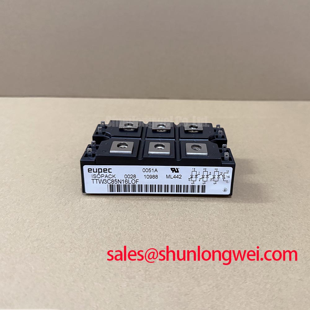
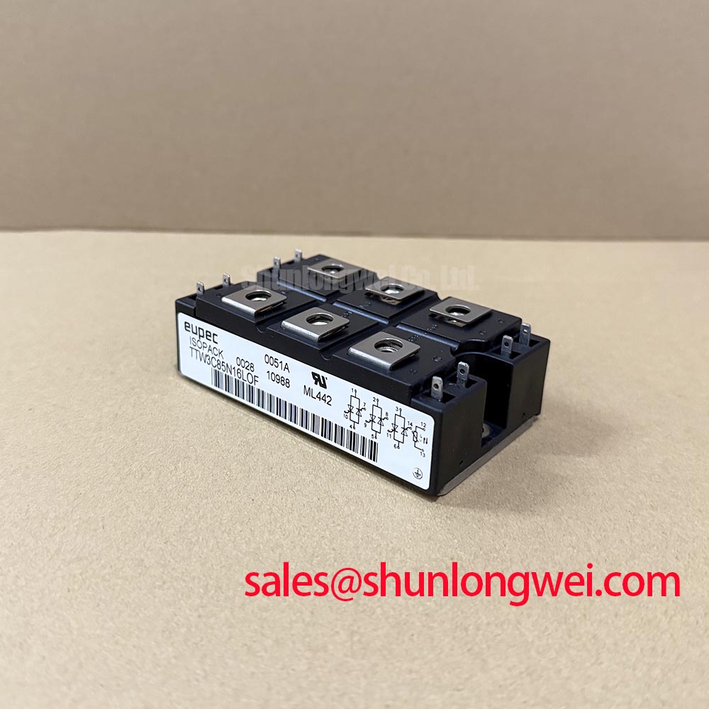
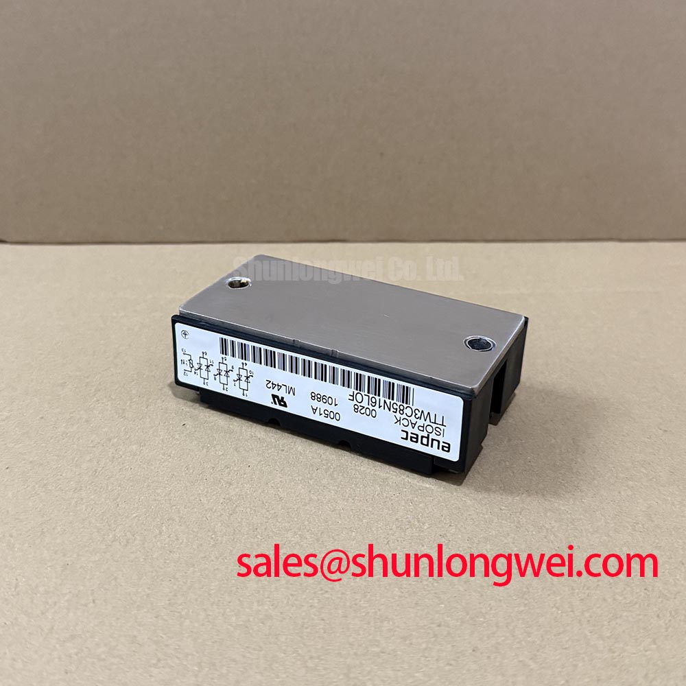
TTW3C85N16LOF | 1600V Thyristor/Diode Module for High-Reliability Industrial Drives
Product Overview & Key Specifications
Engineered for Unmatched Durability with Pressure-Contact Technology
The TTW3C85N16LOF is a high-performance thyristor/diode module designed for robust power control in demanding industrial environments. Its core value proposition lies in a solder-free pressure-contact design that delivers exceptional long-term reliability where conventional modules fail. With specifications of 1600V | 85A (IT(AV)) | Pressure-Contact Design, this module offers superior thermal cycling lifetime and enhanced mechanical robustness. How does pressure-contact technology improve field reliability? It creates a resilient, solder-free interface that eliminates solder fatigue and bond-wire lift-off, the primary failure mechanisms in thermally stressed applications.
Application Scenarios & Value
System-Level Benefits of Solder-Free Design in Demanding Power Control
For high-vibration or thermally cyclic applications like industrial soft starters, the TTW3C85N16LOF's pressure-contact design offers unmatched long-term reliability. Consider a heavy-duty soft starter for a large mining conveyor or crusher. These systems endure constant start-stop cycles, inducing significant thermal stress, alongside persistent mechanical vibration. In such conditions, standard soldered modules are prone to solder fatigue, leading to premature failure and costly downtime. The TTW3C85N16LOF directly mitigates this risk by employing a pressure-mounted structure, ensuring a stable and reliable electrical and thermal connection over an extended operational life. This design philosophy is critical for building power assemblies that meet stringent industrial standards like IEC 61800-5-1.
Its robust 1600V blocking voltage provides a substantial safety margin for equipment operating on 600V and 690V AC lines, common in heavy industry. This ensures resilience against the voltage transients and fluctuations typical of industrial power grids. While the TTW3C85N16LOF excels in line-frequency AC control applications, for high-frequency switching systems such as inverters, a device like the FZ400R17KE3 IGBT module would be the appropriate technology choice.
Key Parameter Overview
Decoding the Specs for Enhanced Operational Lifetime
The technical specifications of the TTW3C85N16LOF are tailored for high-stress power control. The following parameters are crucial for system design and reliability analysis.
| Parameter | Symbol | Value | Conditions |
|---|---|---|---|
| Repetitive Peak Off-State Voltage | VDRM, VRRM | 1600V | Tj = 125°C |
| Average On-State Current | IT(AV) | 85A | TC = 100°C, 180° Sinusoidal |
| RMS On-State Current | IT(RMS) | 134A | TC = 100°C |
| Surge Non-Repetitive On-State Current | ITSM | 1800A | t = 10ms, Tvj = 125°C |
| Critical Rate of Rise of On-State Current | di/dt | 200 A/µs | Tvj = 125°C |
| Threshold Voltage | VT(TO) | 0.95V | Tvj = 125°C |
| On-State Slope Resistance | rT | 3.5 mΩ | Tvj = 125°C |
| Thermal Resistance, Junction to Case | Rth(j-c) | 0.30 °C/W | Per Thyristor/Diode, DC |
| Operating Junction Temperature Range | Tvj | -40 to 125°C |
Download the TTW3C85N16LOF datasheet for detailed specifications and performance curves.
Technical Deep Dive
A Closer Look at Pressure-Contact Mechanics and Their Impact on Reliability
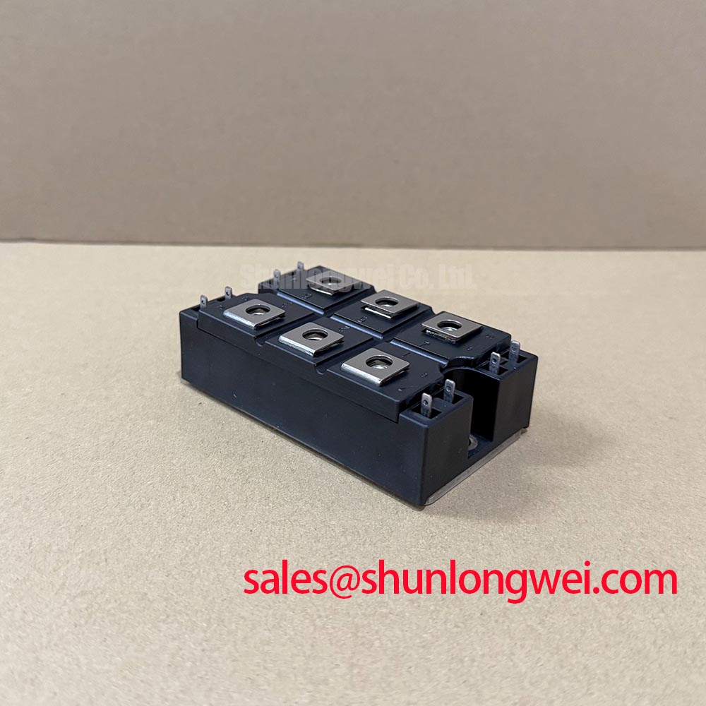
The defining feature of the TTW3C85N16LOF is its internal construction. Unlike conventional modules that rely on multiple layers of soldered materials, this device uses pressure-contact technology. Internally, the silicon die is held under a precise, high clamping force between molybdenum discs and large copper electrodes. This creates an intimate, multi-point connection for both current and heat flow.
The engineering benefit is the elimination of the most common wear-out mechanisms in power electronics: solder fatigue and bond-wire lift-off. In applications with frequent temperature swings, the differing thermal expansion coefficients of silicon, solder, and copper cause immense stress on soldered joints, eventually leading to cracks and failure. The pressure-contact design bypasses this issue entirely. You can conceptualize it like a high-performance brake system in a vehicle; it's engineered for direct, high-pressure contact to manage extreme energy and thermal loads, whereas a solder joint is more akin to a rigid adhesive bond that can crack under repeated stress. This inherent robustness makes it a superior choice for applications where operational lifetime and reliability are non-negotiable, such as in mission-critical power stages or systems deployed in remote or difficult-to-service locations.
Frequently Asked Questions (FAQ)
Engineering Questions on the TTW3C85N16LOF
What is the primary advantage of the pressure-contact design over conventional soldered modules in the field?
The primary advantage is a significantly extended operational lifetime under conditions of thermal cycling. By eliminating solder layers, it circumvents the primary failure mode of solder fatigue and cracking, leading to superior durability in applications with frequent start/stop cycles or wide-ranging ambient temperatures.
How does the 1600V VDRM rating provide a safety margin for systems operating on 690V industrial lines?
A 690V AC line has a peak voltage of approximately 975V (690V * √2). The 1600V rating provides a substantial safety margin of over 60% above this peak operating voltage. This margin is critical for reliably absorbing voltage spikes and transients caused by switching events, lightning, or grid instability without damaging the device.
Can the TTW3C85N16LOF be used for high-frequency inverter applications?
No, this device is a thyristor (SCR), which is designed for line-frequency (50/60 Hz) phase-angle control, rectification, and AC switching. Its turn-off characteristics are not suitable for the high-frequency switching required in modern PWM inverters. For such applications, IGBT modules are the appropriate choice.
What are the key mounting considerations for a pressure-contact module?
Proper mounting is critical. Achieving the correct and evenly distributed clamping force, as specified by the manufacturer, is essential to ensure low thermal and electrical resistance. This typically requires a calibrated mounting clamp and a smooth, flat heatsink surface. Unlike screw-terminal modules, the force applied by the external clamp is what establishes the internal connections and ensures proper operation.
Strategic Considerations for System Design
Integrating the TTW3C85N16LOF is a strategic decision that prioritizes long-term system reliability and reduces the total cost of ownership, particularly in harsh-environment applications. While the initial component selection process may require careful attention to mechanical mounting, the downstream benefits—including reduced field failures, minimized service calls, and enhanced equipment uptime—provide a compelling case for its adoption in next-generation industrial power control, battery charging, and soft starter designs. This technology represents a deliberate shift from minimizing upfront cost to maximizing operational lifetime value.