

Content last revised on September 15, 2026
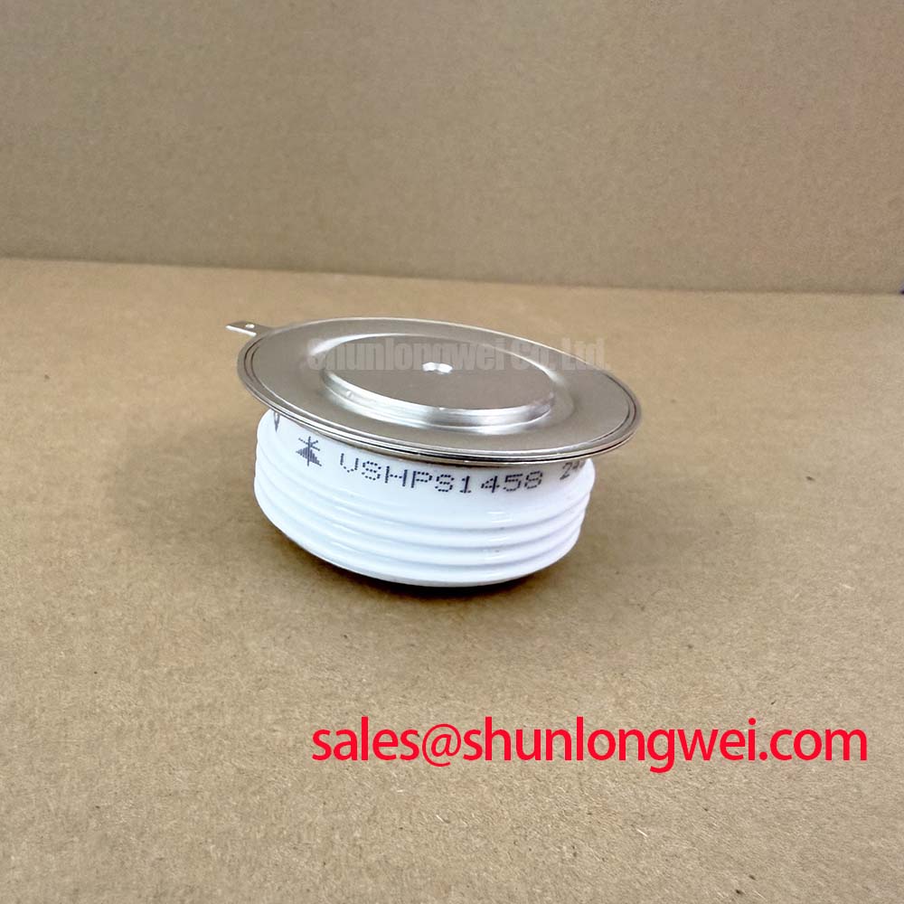
VSHPS1458 Vishay 1600 V 3080 A Thyristor/Diode Module
Confirm the nameplate ratings, inspect the TO-200AC housing, and measure the disconnected power terminals for unintended low impedance before installing VSHPS1458 in a high current converter. This Vishay thyristor/diode module is specified with a repetitive peak off-state voltage of 1600 V, a repetitive peak reverse voltage of 1600 V, and an RMS on-state current of 3080 A at Tc = 25°C.
The official average on-state current is 1650 A at Tc = 55°C. Its peak non-repetitive surge current is 25,700 A at 50 Hz, while the maximum gate trigger voltage is 3.0 V and the maximum gate trigger current is 200 mA. The specified operating junction temperature range is −40°C to +125°C. The package housing outline is TO-200AC, also identified as K-PUK or A-24.
| Parameter | Official rating |
| Repetitive peak off-state voltage, VDRM | 1600 V |
| Repetitive peak reverse voltage, VRRM | 1600 V |
| RMS on-state current, Tc = 25°C | 3080 A |
| Average on-state current, Tc = 55°C | 1650 A |
| Peak non-repetitive surge current, 50 Hz | 25,700 A |
| Maximum gate trigger voltage, VGT | 3.0 V |
| Maximum gate trigger current, IGT | 200 mA |
| Operating junction temperature, Tj | −40°C to +125°C |
| Housing | TO-200AC, K-PUK / A-24 |
Field Diagnostics & Commissioning: ITSM Safety Derating across Repetitive Mains in VSHPS1458 Topologies
During commissioning, record the actual cooling conditions at the mounting surface rather than evaluating the current rating in isolation. The 25,700 A ITSM value is a peak non-repetitive surge rating at 50 Hz, not a continuous operating target. Repetitive fault events, delayed clearing, and elevated case temperature require review against the complete Vishay data sheet and the selected semiconductor fuse coordination data.
For a medium-frequency induction melting or hardening furnace, inspect the AC input path, firing circuit, semiconductor fuses, and busbar joints before applying load. Check that the fuse I²t coordination data is appropriate for the actual fault-clearing arrangement; the module rating alone does not establish a suitable protection scheme. After a protection event, measure the gate and main terminals against a known-good reference and verify that reverse voltage is not reapplied until the circuit has been isolated and the junction condition assessed.
The TO-200AC housing requires a mechanically stable, electrically clean mounting interface. The installer should verify the manufacturer’s specified mounting method, contact flatness, thermal interface condition, and terminal hardware requirements for the exact assembly. A general mounting torque value should not be presented as an official VSHPS1458 rating unless it is confirmed by the applicable mechanical drawing.
Maintenance Note: De-energize and isolate the furnace before cleaning the heatsink, checking terminal tightness, or disconnecting the gate wiring, then monitor contact temperature during controlled commissioning.
Benchtop Waveform Tuning: Mitigating Stress via Turn-On Current Rise Limiting
Use an oscilloscope to examine the gate pulse, anode-to-cathode voltage, and load current together during the first low-energy tests. A clean gate command does not by itself confirm that the power circuit is switching within safe system limits. Stray inductance in the busbar and gate loop can produce voltage overshoot, ringing, or uneven current sharing, particularly in high-current furnace converters.
An RC snubber can be evaluated across the relevant power terminals when measured commutation waveforms show excessive ringing or rapid voltage transitions. The resistor and capacitor values must be selected from the measured circuit impedance, switching frequency, expected energy, capacitor pulse capability, and thermal behavior. These are system-level design values, not factory parameters of VSHPS1458. A series saturable reactor may also be considered where the topology requires controlled current rise, but its core behavior and reset conditions must be verified under the actual repetitive waveform.
Keep the gate wiring short and physically separated from high-current commutation paths. Minimize parasitic loop inductance to reduce gate oscillation and unintended triggering, then validate the result with the oscilloscope at the module terminals. Where a gate-driver circuit uses active clamping or Miller-related transient control, the engineer should verify the clamp threshold, pulse energy, and transient response against the actual gate characteristics; no internal gate charge or capacitance value is specified in the supplied VSHPS1458 parameters.
The external gate-drive layout should follow the principles described in Precision Gate Drive Design. The referenced guidance can support layout review, while the final pulse shape, snubber network, and current-rise control remain dependent on the complete converter.
VSHPS1458 Circuit Protection & Reliability: Calibrating IEC 61000-4-5 Industrial Surge Immunity
Assess surge protection at the equipment level rather than treating the thyristor/diode module as an independently certified surge protector. IEC 61000-4-5 testing and immunity performance depend on the complete input network, coupling path, enclosure, grounding arrangement, protective devices, and test configuration. VSHPS1458 should therefore be evaluated as one part of the furnace power stage.
For an AC input protection review, map the location of semiconductor fuses, MOVs, RC snubbers, contactors, and isolation devices relative to the module terminals. The MOV selection should account for the normal line voltage, temporary overvoltage, surge energy, coordination with upstream protection, and the maximum voltage the thyristor junction can tolerate during the event. The applicable surge test level and acceptance criteria must be confirmed by the equipment designer and the relevant compliance plan.
Inspect the busbar stack for loose joints, contamination, discoloration, or changes in contact pressure. A laminated or closely coupled bus structure may help reduce commutation loop inductance, but the resulting peak voltage must be verified during switching tests. The same review should include thermal cycling, condensation control, and heatsink airflow because the official current ratings are tied to stated case-temperature conditions.
When the furnace includes an upstream rectifier or auxiliary conversion stage, engineers may evaluate the related SKKH330/08E device according to its own published specifications. It should not be treated as an automatic electrical substitute or guaranteed companion for VSHPS1458. For broader power-semiconductor context, consult Vishay Siliconix Industrial Power MOSFETs; MOSFET data should not be transferred to this thyristor/diode module.
VSHPS1458 Operational Boundaries: Evaluating Gate Trigger Current Dynamics
The official maximum gate trigger current is 200 mA, and the maximum gate trigger voltage is 3.0 V. These values define important gate-drive limits, but they do not provide a complete firing-pulse recipe. The driver must be checked for source impedance, pulse duration, isolation, repetitive duty, return-path integrity, and behavior during supply variation.
Use a differential probe or an appropriately isolated measurement method to inspect the gate-to-cathode waveform directly at the module. Confirm that the delivered pulse reaches the intended trigger condition without excessive ringing or ground-reference movement. If a multi-pulse firing method is considered, the timing and repetition must be validated against the controller, transformer or isolator, thermal conditions, and the actual commutation sequence.
Do not assume a specified gate current slope, holding-current value, or gate hotspot limit when it is absent from the supplied factory parameter set. The system engineer should obtain those values from the applicable Vishay documentation or device-specific application data before using them for protection calculations. Gate-loop parasitic inductance should be minimized, and the firing return should remain separate from high-current power paths wherever the mechanical layout permits.
For replacement evaluation, compare the electrical ratings, housing outline, terminal arrangement, cooling interface, and firing requirements with the original assembly. The VS-ST730C18L0 may be reviewed as a separate Vishay device for cross-model assessment, but compatibility must be established from its own data sheet and the furnace topology rather than from current or voltage labels alone.