
Content last revised on September 10, 2026
2MBI100U4H-170-50 Thermal-Electrical Optimization: High dv/dt Cross-Conduction Shoot-Through Practical Tuning
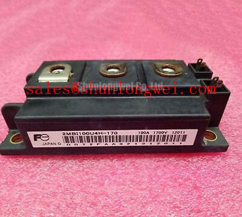
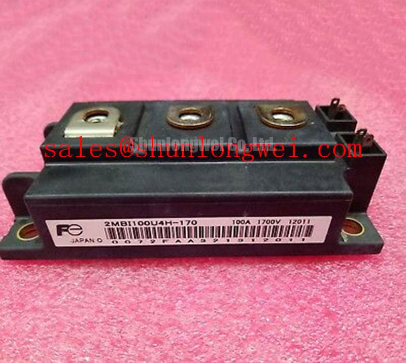
Verify the module marking against the equipment record, inspect the baseplate and terminals for mechanical damage, and confirm the inverter’s electrical boundary before applying any gate or collector voltage. The Fuji Electric 2MBI100U4H-170-50 is an IGBT module specified for a 1700 V collector-emitter voltage, with a 100 A continuous collector current at TC = 80°C and a 200 A pulsed collector current.
For maintenance teams evaluating a failed power stage, the first practical checks are isolation from the DC bus, visual inspection of the housing, terminal condition, and comparison of the gate-emitter and collector-emitter impedance with a known-good unit. These checks do not by themselves prove semiconductor health, but they help identify whether the next investigation should focus on the module, gate driver, busbar assembly, cooling path, or switching control.
| Parameter | Specification | Classification |
|---|---|---|
| Collector-Emitter Voltage, VCES | 1700 V | Official Datasheet Specification |
| Continuous Collector Current, IC at TC = 80°C | 100 A | Official Datasheet Specification |
| Pulsed Collector Current, ICP | 200 A | Official Datasheet Specification |
| Isolation Voltage, Viso, AC 1 min | 4000 V | Official Datasheet Specification |
| IGBT Thermal Resistance, Rth(j-c) | 0.20 K/W | Official Datasheet Specification |
| Maximum Junction Temperature, Tj max | 150°C | Official Datasheet Specification |
| Baseplate Mounting Torque | 2.5 to 3.5 N·m | Design Consideration for M5 screws |
When this module is evaluated in a high-power central photovoltaic inverter, regenerative braking chopper, or bidirectional DC-DC stage, the gate-drive circuit must be treated as part of the switching power loop. The module’s official ratings define voltage, current, isolation, thermal resistance, and junction-temperature limits; they do not define a complete gate-driver timing solution for every converter topology.
High dv/dt at the switching node can couple through the device’s internal capacitances and the external gate-drive layout. A transient gate voltage on the complementary device may reduce the effective dead time and create cross-conduction. This is a system-level switching behavior, not a standalone rating of the 2MBI100U4H-170-50. Designers should observe both gate-emitter waveforms and collector-emitter voltage at the module terminals while checking the actual driver propagation delay, turn-off behavior, isolation barrier response, and common-emitter coupling.
A low-impedance active Miller clamp may be evaluated where the gate driver supports it. The clamp path should be physically short and referenced to the correct emitter return used by the gate driver. If a negative gate bias is selected, its voltage, transition behavior, and absolute limits must be verified against the original driver documentation and the module’s applicable gate-emitter requirements. The values cannot be assumed from the collector voltage rating.
Dead time should be established from measured turn-off and turn-on behavior across temperature, load current, bus voltage, and gate resistance conditions. A short protection blanking interval can allow a false turn-on or desaturation event to pass unnoticed, while an excessive interval can increase switching loss. The correct setting is therefore system-determined and should be validated on the assembled inverter rather than copied from an unrelated IGBT design.
For a regenerative braking chopper, the braking resistor and its switching path must absorb the energy delivered by the mechanical load without allowing the DC bus to exceed the converter’s validated voltage margin. The module can be assessed as the switching element in that path, but resistor energy capacity, chopper frequency, thermal airflow, and bus-control strategy remain equipment-level decisions. During fault reproduction, use a current-limited test arrangement and compare the measured transient with the switching device’s validated operating area.
Assembly Integrity & Layout Architecture: Implementing Differential Gate-Emitter Loop Routing
Before replacing a module, record the original power-terminal arrangement and gate-driver wiring. Do not infer terminal polarity or auxiliary emitter identity from a visually similar package. Confirm the pin and terminal definition from the applicable Fuji Electric documentation and the equipment schematic, then check continuity with the DC bus isolated and discharged.
The gate loop should be routed as a compact forward-and-return pair. The driver return must follow the intended emitter reference instead of sharing a long, high-current emitter path. Mutual coupling from the main collector-emitter current can shift the apparent emitter potential seen by the driver. That shift may appear on an oscilloscope as gate ringing, delayed turn-off, or an unexpected difference between the driver output and the voltage measured directly at the module terminals.
Use differential probing at the module rather than relying only on the driver-board test point. The probe reference, isolation method, and bandwidth should be suitable for the switching environment. Engineers should compare the gate-emitter waveform during normal operation, turn-off, fault interruption, and restart. If the waveform differs substantially between the driver output and the module pins, inspect the gate cable, emitter return, connector contacts, and mechanical routing before changing control parameters.
High-voltage creepage and clearance must be checked in the complete assembly, including busbar edges, screws, insulating barriers, contamination paths, cable lugs, and the module housing. The specified 4000 V AC for one minute is an official isolation-voltage specification; it does not replace the system designer’s insulation coordination review. Pollution level, working voltage, transient environment, material group, enclosure condition, and applicable equipment standards influence the final spacing decision.
Baseplate flatness, heatsink cleanliness, and even fastener loading directly affect the thermal interface. The stated 2.5 to 3.5 N·m mounting torque is a design consideration for M5 screws, not a substitute for the equipment manufacturer’s assembly procedure. Tighten progressively using calibrated tools, keep washers and mounting surfaces clean, and inspect for distortion that could create uneven thermal contact.
Maintenance Note: De-energize and verify the DC bus is discharged before touching gate, power, or auxiliary terminals, then monitor contact temperature and inspect the cooling airflow during scheduled service.
In a vibrating cabinet, busbars should be supported so that terminal studs do not carry cable mass or repeated mechanical stress. Recheck fastener condition, conductor discoloration, and signs of localized heating during preventive maintenance. A loose connection may produce intermittent voltage overshoot or thermal imbalance, but the observed symptom should be confirmed by torque inspection, thermal measurement, and waveform comparison rather than assigned to a single cause.
For topology-level coordination, the 2MBI200UB-120 can be reviewed as a separately specified device in an upstream or auxiliary power stage. It should not be treated as an automatic substitute for the 2MBI100U4H-170-50; voltage, current, switching role, mechanical fit, gate-drive requirements, and thermal conditions must be checked independently.
2MBI100U4H-170-50 Operational Boundaries: Mitigating Hard-Switching Transients
Hard-switching evaluation should begin with the actual collector-emitter waveform at the module, the gate-emitter waveform, current commutation path, and DC-bus measurement. The official 1700 V VCES rating is an electrical boundary for the device. It does not authorize operation at that voltage under arbitrary overshoot, switching speed, temperature, short-circuit duration, or stray-inductance conditions.
A short-circuit protection system should detect abnormal current or desaturation, block the affected gate, and prevent repeated restart until the fault logic has completed its defined sequence. The suggested response interval must come from the gate-driver and protection architecture, because the supplied module parameters do not establish a universal short-circuit withstand time. Any reference to a sub-microsecond or microsecond-level response should therefore be treated as a system engineering target requiring bench validation, not as a Fuji Electric module specification.
Two-stage soft turn-off may be evaluated to reduce the voltage excursion caused by abruptly interrupting a high fault current. The first stage limits the rate of current change, while the second stage completes gate discharge after the driver confirms that the fault state is stable. The actual gate resistance, clamp behavior, delay, and fault-reset policy must be selected from measured waveforms and the driver manufacturer’s limits.
When a switching transient appears, inspect the complete commutation loop rather than changing the gate resistor in isolation. Check DC-link capacitor placement, busbar overlap, diode recovery behavior, driver supply stability, gate-emitter return routing, and probe technique. The relationship between stray inductance and current slew rate explains why a faster current transition can create a larger inductive voltage excursion, but the acceptable peak must be established by testing the assembled converter against its validated DC-bus limit.
For large photovoltaic inverter service work, the module may be considered in a 1500 V class DC-link environment only after the integrator verifies topology, switching transient margin, insulation coordination, cooling capability, and protection response. A nominal comparison between a 1500 V system label and a 1700 V device rating is not sufficient evidence of compatibility. The inverter’s worst-case open-circuit condition, control fault, grid event, DC-bus regeneration, and parasitic overshoot all require review.
The Fuji Electric Global Power Semiconductor Technologies resource should be consulted for manufacturer-level semiconductor information, while the equipment service record remains necessary for confirming the original gate-drive and protection implementation.
2MBI100U4H-170-50 Circuit Protection & Reliability: Calibrating DC-Bus Operating Voltage Headroom Derating
DC-bus headroom should be calibrated from measured operating conditions, not from the part number alone. Record the maximum steady-state bus voltage, switching overshoot, transient duration, ambient temperature, heatsink temperature, and fault response. The 1700 V collector-emitter specification and 150°C maximum junction-temperature specification are official device limits, while the permitted operating margin under a particular inverter fault condition must be established by the system designer.
Altitude and environmental conditions can alter the insulation design of the cabinet, cooling performance, and air-clearance requirements. A general altitude statement cannot be converted into a specific semiconductor derating curve without an authoritative source for the complete assembly and application. For installations above 2000 m, engineers should review the inverter manufacturer’s altitude rules, insulation coordination, enclosure pressure and contamination conditions, thermal derating, and cooling-air capability.
Terrestrial neutron effects and single-event burnout are high-risk reliability topics that require device-specific qualification data, mission profile information, geographic exposure assumptions, and an appropriate reliability methodology. No FIT rate, burnout probability, operating-life figure, or fixed DC-bus reduction should be assigned to this module without a traceable Fuji Electric document, recognized reliability standard, or application white paper. In the absence of that source, the correct engineering action is to characterize the voltage environment and consult the device manufacturer or system safety authority.
Maintenance teams can still reduce avoidable stress by checking heatsink fouling, fan performance, condensation evidence, cabinet heaters, thermal-interface condition, and terminal discoloration. The official 0.20 K/W Rth(j-c) value describes the IGBT junction-to-case thermal path under its specified conditions; it does not represent total junction-to-ambient performance. Case temperature measurement, heatsink resistance, interface quality, airflow, and enclosure temperature must be considered together.
When a higher-current alternative is reviewed, the 2MBI400U4H-170 should be treated as a separate engineering candidate rather than an assumed replacement. Confirm its electrical ratings, internal configuration, gate-drive behavior, mounting geometry, thermal path, and protection coordination against the original application before any change is approved.
For switching systems that include resonant or quasi-resonant operating intervals, the guide Resonant Topologies in Home Appliances provides useful topology context. It should be used to frame circuit behavior, not to replace the module’s own datasheet limits or the inverter manufacturer’s validation procedure.
During final acceptance testing, verify gate timing, dead-time behavior, soft turn-off response, bus voltage, collector-emitter overshoot, thermal rise, and isolation performance under representative load conditions. Any change in gate-loop routing, cooling hardware, DC-link construction, or protection firmware should trigger a fresh review of these measurements.