
Content last revised on June 3, 2026
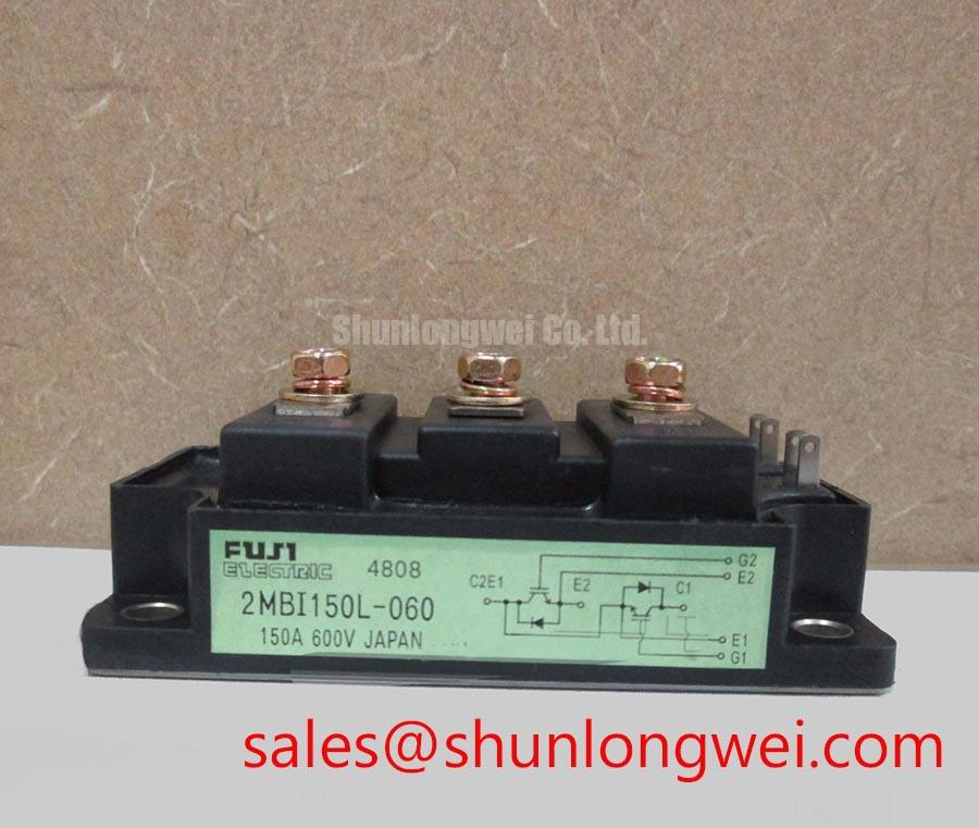
2MBI150L-060 Fuji Electric 600V 150A Dual IGBT Module
Engineering-Grade Power Switching for Industrial Drives
Proven 600V/150A Half-Bridge Topology with Established Thermal Robustness
The Fuji Electric 2MBI150L-060 is a 600V, 150A dual (2-in-one) IGBT module from the L-Series, engineered for hard-switching industrial converters where field-proven reliability outweighs cutting-edge speed. With a typical VCE(sat) of approximately 2.5V and an isolated baseplate rated to 2500V AC, it remains a workhorse for retrofit and legacy motor-drive platforms. What makes this module suitable for sustained operation? Its conservative die area, mature N-channel planar gate structure, and robust solder/wire-bond construction deliver predictable power-cycling behavior at switching frequencies up to roughly 20 kHz. For 400V-class three-phase inverters needing 150A continuous output, the 2MBI150L-060 remains a dependable building block.
Application Scenarios & Value
Translating L-Series Characteristics into Reliable Motor and UPS Power Stages
Engineers often face a recurring trade-off in industrial inverter design: high starting torque requires headroom in collector current, while continuous duty demands tight control over conduction losses. The Fuji Electric 2MBI150L-060 addresses this by combining a 150A nominal IC rating with a typical pulsed current capability of 300A, giving designers a 2x overload margin to handle motor inrush currents in 22–37 kW Variable Frequency Drives (VFDs) without nuisance trips.
Best fit: for 400V-class three-phase industrial inverters and UPS systems requiring 150A continuous current with high thermal margin, this 600V dual module is a proven choice.
- General-purpose AC motor drives for pumps, fans, compressors and conveyors operating from 380–415 V lines.
- Online and line-interactive UPS in the 10–30 kVA class, leveraging the dual half-bridge structure to simplify three-phase inverter stages.
- Industrial welding power supplies and induction heating front-ends operating below 20 kHz, where conduction loss dominates.
- Servo amplifiers and legacy CNC equipment requiring drop-in compatibility with established L-Series footprints.
For higher current density in the same 600V class, the related 2MBI200L-060 raises IC to 200A in a similar package, while the U2A-Series 2MBI150U2A-060 offers a newer trench-gate generation for designers prioritizing reduced switching loss. Our team helps engineers benchmark these options through our IGBT selection guide.
Technical Deep Dive
Why the L-Series Thermal Path Still Matters in Modern Retrofits
The 2MBI150L-060 uses an AlN-based DCB substrate and a copper baseplate, a construction that yields a junction-to-case thermal resistance suitable for forced-air-cooled assemblies. Think of thermal resistance as a power "highway": a low Rth(j-c) is a wider lane, allowing more heat to flow from the silicon to the heatsink before traffic (temperature) backs up. Because the L-Series operates with planar IGBT cells, its VCE(sat) exhibits a slightly negative temperature coefficient at low currents and positive at rated load — a behavior that aids passive current sharing when paralleling modules, though strict layout symmetry remains essential.
Switching energy (Eon + Eoff) for this generation is higher than for modern 7th-generation IGBT devices, meaning designers should keep the inverter switching frequency at or below 15–20 kHz to stay within the safe thermal envelope. Our engineering library covers this trade-off in detail in our discussion on Rth and heatsink design.
What is the primary benefit of the L-Series construction? Predictable long-term power-cycling capability in legacy 600V industrial platforms.
Key Parameter Overview
Functional Grouping of Electrical, Thermal and Mechanical Ratings
| Group | Parameter | Value |
|---|---|---|
| Absolute Maximum | Collector–Emitter Voltage (VCES) | 600 V |
| Collector Current (IC, DC @ Tc=25°C) | 150 A | |
| Peak Collector Current (ICP) | 300 A | |
| Electrical | Collector–Emitter Saturation Voltage (VCE(sat), typ.) | ~2.5 V |
| Gate–Emitter Voltage (VGES) | ±20 V | |
| Thermal | Junction Temperature (Tj, max) | 150 °C |
| Operating / Storage Temp. | -40 to +125 °C | |
| Mechanical | Isolation Voltage (Viso, 1 min, AC) | 2500 V |
| Configuration | Dual (Half-Bridge, 2-pack) |
Download the 2MBI150L-060 datasheet for detailed specifications and performance curves.
Frequently Asked Questions
What maximum switching frequency does the 2MBI150L-060 realistically support in a hard-switched VFD?
Because the L-Series uses an earlier IGBT cell technology with higher Eon/Eoff than modern trench devices, most designs keep PWM frequencies between 4 kHz and 15 kHz to preserve thermal margin at rated load.
How does the 2500V AC isolation rating influence creepage and PCB layout?
The reinforced isolation simplifies compliance with UPS and industrial drive safety standards, allowing the heatsink to be grounded directly while reducing the need for additional insulating barriers around the baseplate.
Is the 2MBI150L-060 a direct replacement for newer U2A or V-Series modules?
Mechanically the footprint is similar within Fuji's standard package family, but switching characteristics differ. Validation of gate-drive timing, dead-time and thermal performance is required before any cross-generation substitution.
For pricing, lead-time, and traceability documentation on the Fuji Electric 2MBI150L-060, contact our sales team for a tailored quotation.