

Content last revised on September 10, 2026
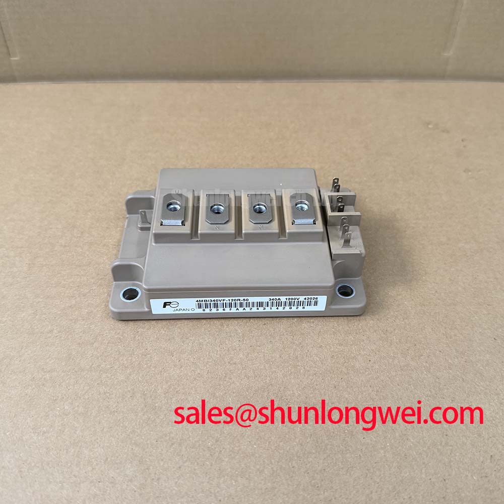
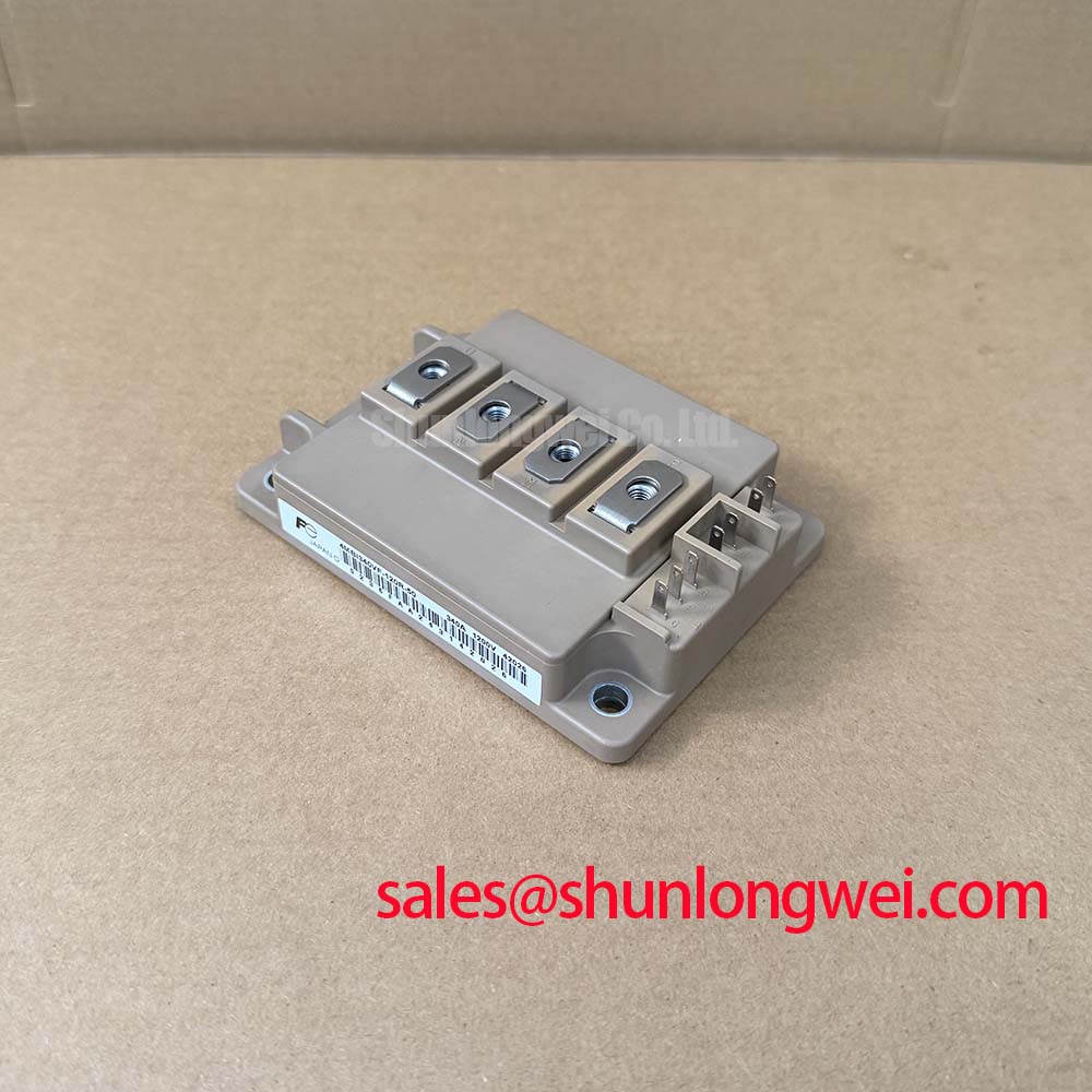
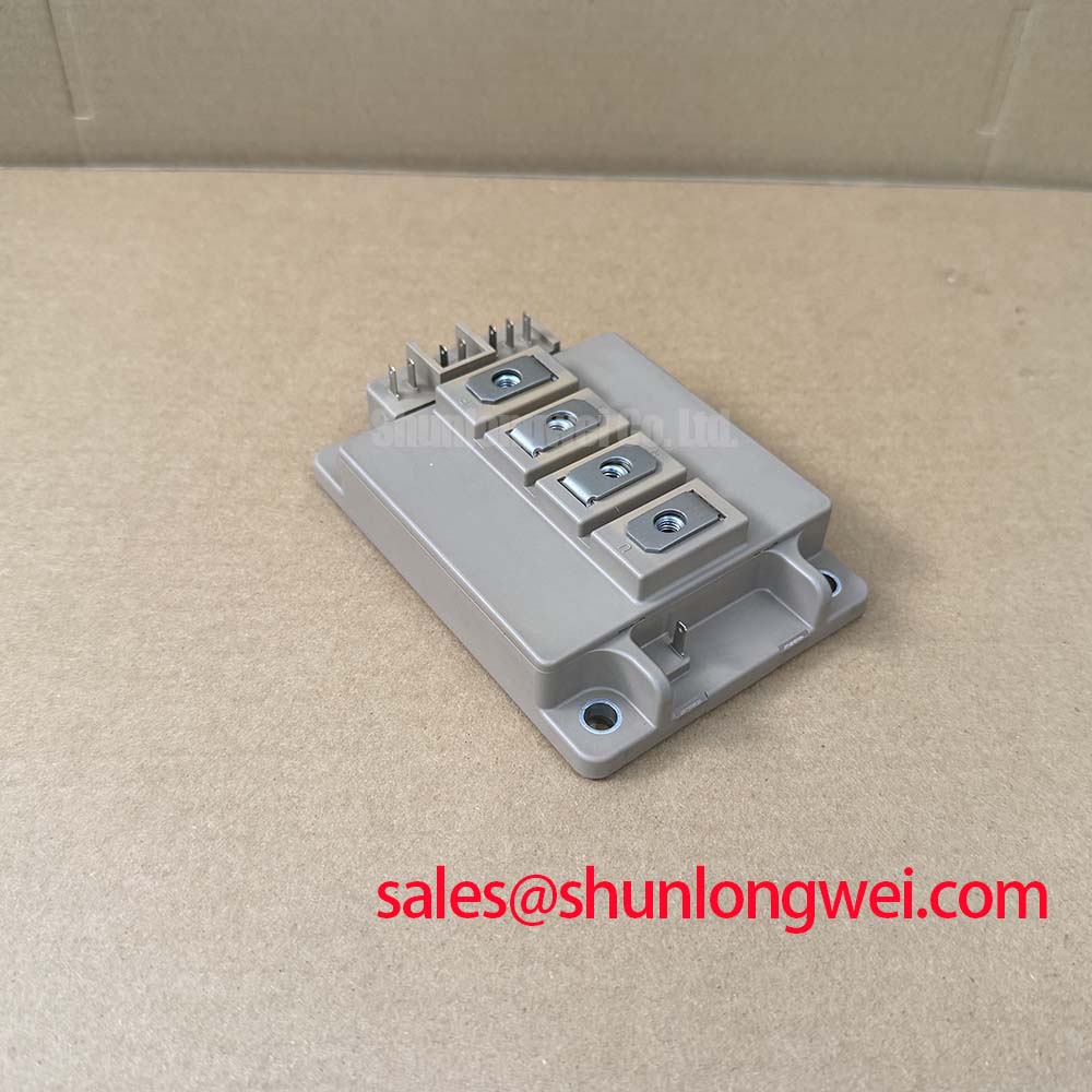
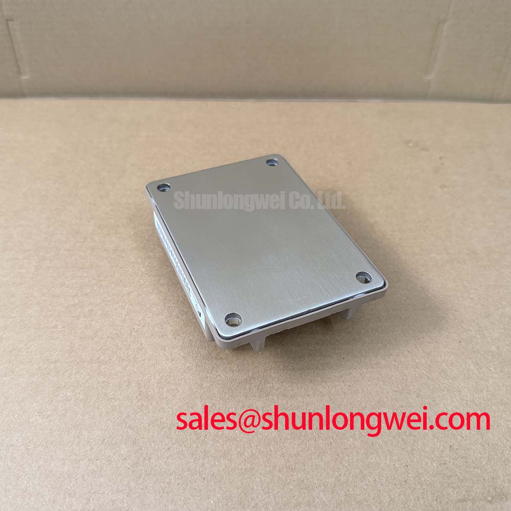
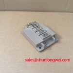
4MBI340VF-120R-50 Fuji Electric T-Type NPC 3-Level IGBT Module | 1200V 340A
How do design engineers minimize switching losses in grid-tied solar inverters without increasing thermal overhead? The Fuji Electric 4MBI340VF-120R-50 T-type NPC 3-level circuit module addresses this issue directly, operating with a maximum collector-emitter voltage of 1200V and a nominal current rating of 340A. Top Specifications: 1200V | 340A | M403 package. Key Benefits: Reduced switching losses | Optimized footprint. By utilizing reverse-blocking technology in the neutral clamp path, this module mitigates the high conduction losses typically associated with standard three-level topologies. For 3-level solar inverters prioritizing efficiency, the 1200V 4MBI340VF-120R-50 is the optimal choice.
Frequently Asked Questions
Direct Answers to Key Technical Queries
How does the integrated RB-IGBT in the 4MBI340VF-120R-50 optimize efficiency?
By eliminating series diode voltage drops in the bidirectional neutral clamping path, it lowers conduction losses. What is the primary benefit of its T-type topology? Reduced switching losses compared to standard 3-level NPC configurations.
What is the engineering significance of the 2500V AC isolation voltage rating?
This isolation rating guarantees safety and system reliability under transient overvoltage conditions, preventing dielectric breakdown between the active silicon chips and the copper baseplate during grid disturbances.
Key Parameter Overview
Decoding the Specs for Enhanced Thermal Reliability
The electrical and thermal specifications of the 4MBI340VF-120R-50 are grouped below to facilitate rapid engineering assessment:
| Function Group | Parameter Symbol | Specification Value | Engineering Significance |
|---|---|---|---|
| Main Switch (T1, T4) | VCES | 1200V | Max blocking voltage for high-voltage DC link rails. |
| IC | 340A | Nominal collector current capacity at continuous operation. | |
| Neutral Switch (T2, T3) | VCES | 600V (RB-IGBT) | Optimized voltage rating for bidirectional clamping path. |
| IC | 340A | Identical current capacity for balanced neutral current flow. | |
| Thermal & Isolation | Tj | Up to 150°C | Extended junction temperature headroom for reliable operation. |
| Viso | 2500V AC (1 min) | High isolation barrier ensuring safety and EMI mitigation. | |
| Package | Mechanical Form | M403 package | Low-inductance terminal layout for fast switching transitions. |
Download the 4MBI340VF-120R-50 datasheet for detailed specifications and performance curves.
Technical & Design Deep Dive
Optimizing Switching Loss via Integrated RB-IGBT Technology
The core innovation of the 4MBI340VF-120R-50 lies in its V-series trench-gate structure combined with a T-type Neutral Point Clamped (NPC) 3-level inverter configuration. Unlike standard NPC setups that require multiple diodes in series, the T-type NPC uses 1200V IGBTs for the main switching transitions and 600V Reverse Blocking IGBTs (RB-IGBTs) for the bidirectional neutral path. Think of the T-type NPC topology as a high-speed bypass lane on a highway: it allows current to flow directly to the neutral point with minimal resistance, bypassing unnecessary series components to minimize conduction losses. The Fuji Electric V-Series IGBT utilizes thin-wafer technology to balance the trade-off between collector-emitter saturation voltage VCE(sat) and turn-off switching losses Eoff.
Engineers implementing high-efficiency power stages must prioritize low stray inductance. The M403 package features an optimized terminal configuration that minimizes loop area, significantly reducing transient voltage overshoot during rapid turn-off phases. How does the integrated RB-IGBT improve efficiency? By eliminating series diode voltage drops in the bidirectional neutral clamping path. This design consideration is critical for preventing device degradation, as explored in detailed IGBT failure analysis documentation. In addition, the direct bonding of the silicon chips to an alumina substrate ensures low thermal resistance. A lower thermal resistance acts like a wider copper thermal pipeline, allowing heat to escape from the silicon junction to the heatsink rapidly, preventing thermal bottlenecks. Understanding these thermal properties is crucial for successful IGBT thermal management. For a detailed guide on selecting a high-power IGBT Module, refer to our in-depth analysis of IGBT modules.
Application Scenarios & Value
Achieving System-Level Benefits in High-Frequency Power Conversion
The 4MBI340VF-120R-50 is designed for power conversion systems where efficiency and compact layout are paramount. It is commonly deployed in grid-tied solar inverters, uninterruptible power supply (UPS) systems, and industrial power conditioners. In these systems, switching frequencies typically range from 8 kHz to 16 kHz, where the low turn-on and turn-off losses of the V-series chip technology provide measurable efficiency gains. For instance, in a 50kW solar inverter design, the lower conduction loss of the RB-IGBT in the clamping path directly translates to lower operating temperatures under high-load conditions, permitting the use of smaller heatsinks and lowering the total cost of ownership (TCO).
For systems requiring higher current handling capacity, the related 4MBI900VB-12R1-61 or 1MBI600VF-120-50 can be evaluated. Engineering teams should carefully balance the gate drive parameters to ensure clean switching waveforms without excessive electromagnetic interference (EMI).
To evaluate how this module fits your system-level thermal and efficiency targets, contact our technical sales team for comprehensive specification support and inventory availability.