
Content last revised on October 15, 2026
4R3TI60Y 080 Circuit Protection and Reliability: Calibrating Mechanical Mounting Torque Sequence and Thermal Contact
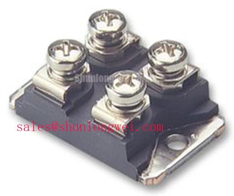
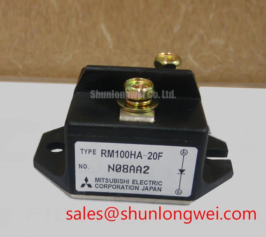
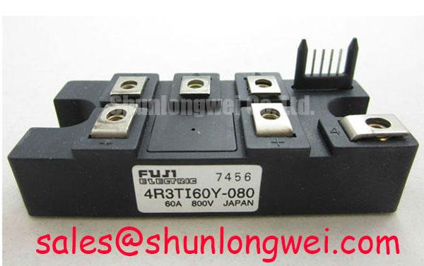
When a diode module is removed from an SVC or thyristor switched capacitor cabinet, record the terminal arrangement, inspect the copper baseplate contact pattern, and compare the replacement markings before reconnecting the power circuit. The 4R3TI60Y 080 is a Fuji Electric diode module with an official rated current of 60.0 A and a Fuji Power Diode package. Its operating voltage is identified as a Standard Industrial Rating in the supplied product data; the voltage requirement of the original circuit must remain within the equipment documentation and approved coordination study.
For a grid tied static Var compensator or thyristor switched capacitor assembly, the diode should be assessed as part of the complete commutation, protection, and thermal path. Confirm polarity, terminal identification, busbar clearance, and the current path through the original schematic. The component itself does not establish the voltage, surge, EMC, or system insulation rating of the finished installation.
Thermal contact should be checked before electrical commissioning. Remove old thermal compound completely, inspect the heatsink for burrs or uneven machining, and apply a consistent thin layer suitable for the approved thermal interface process. Place the diode module squarely on the copper surface, start all mounting fasteners by hand, and tighten progressively in a diagonal sequence so that the baseplate is not twisted during seating.
The key field observation is the contact pattern after controlled assembly. Uneven compound spread, a visible dry region, or a concentrated imprint near one corner may indicate mechanical distortion or a heatsink flatness issue. Recheck the heatsink surface, mounting hardware, and terminal alignment before energization. Thermal resistance from junction to case, written as Rth(j-c), is one part of the complete thermal path; interface and heatsink resistance must also be considered. The service record should include heatsink cleanliness, interface material condition, fastening sequence, and measured contact temperature during a controlled load test.
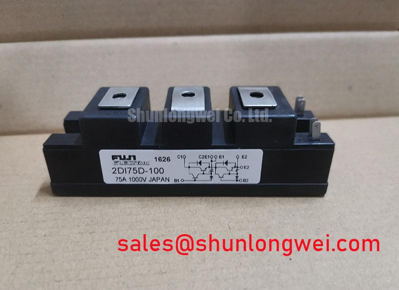
Fuse coordination belongs to the protection review rather than to the diode label alone. Select a semiconductor fuse using the applicable manufacturer coordination information, then compare its clearing I2t with the diode module withstand data for the intended fault path. The prospective fault current, upstream impedance, fuse location, and switching arrangement all influence the result. The 2DI300A 050 may be reviewed as a separate high current power diode module within a related rectification stage, but any substitution or complementary use requires a terminal, voltage, current, and thermal compatibility review.
Maintenance Note: Monitor contact temperature during scheduled operation and inspect the heatsink airflow path whenever dust accumulation or thermal interface aging is suspected.
Assembly Integrity and Layout Architecture: Controlling Off State Voltage Rise in 4R3TI60Y 080 Circuits
Control of the off state voltage rise starts with the physical commutation loop. Keep the forward and return conductors arranged to reduce unnecessary loop area, maintain firm busbar joints, and prevent loose terminal hardware from adding changing contact resistance during thermal cycling. In a capacitor switching cabinet, the diode, thyristor, fuse, snubber, and capacitor branch should be reviewed as one current transfer network.
An RC snubber can be evaluated when measured switching waveforms show excessive ringing or an unwanted voltage rise across the semiconductor. The resistor and capacitor values should be selected from the actual circuit inductance, switching frequency, capacitor characteristics, and verified voltage waveform. A series saturable reactor may also be considered where the topology requires control of the initial current rise. These are system design decisions, not fixed specifications of the 4R3TI60Y 080.
Use a differential voltage probe and suitable current measurement during commissioning to examine the switching event at the device terminals. Compare the observed peak and ringing with the approved device voltage boundary and the cabinet protection study. Cable routing, busbar overlap, snubber placement, and probe connection technique can materially change the displayed waveform. The applicable diode safety and operating terminology should be interpreted alongside IEC 60747 2 Semiconductor Diodes Standard.
For a service replacement, document the original lead dress and busbar position before removal. The Fuji Electric semiconductor portal provides broader manufacturer context for power semiconductor product families at Fuji Electric Power Semiconductors Portal. A compatible mechanical outline alone is not sufficient evidence of electrical suitability.
| Selection reference | Manufacturer | Category | Official rated current | Package information |
|---|---|---|---|---|
| 4R3TI60Y 080 | Fuji Electric | Diode Module | 60.0 A | Fuji Power Diode |
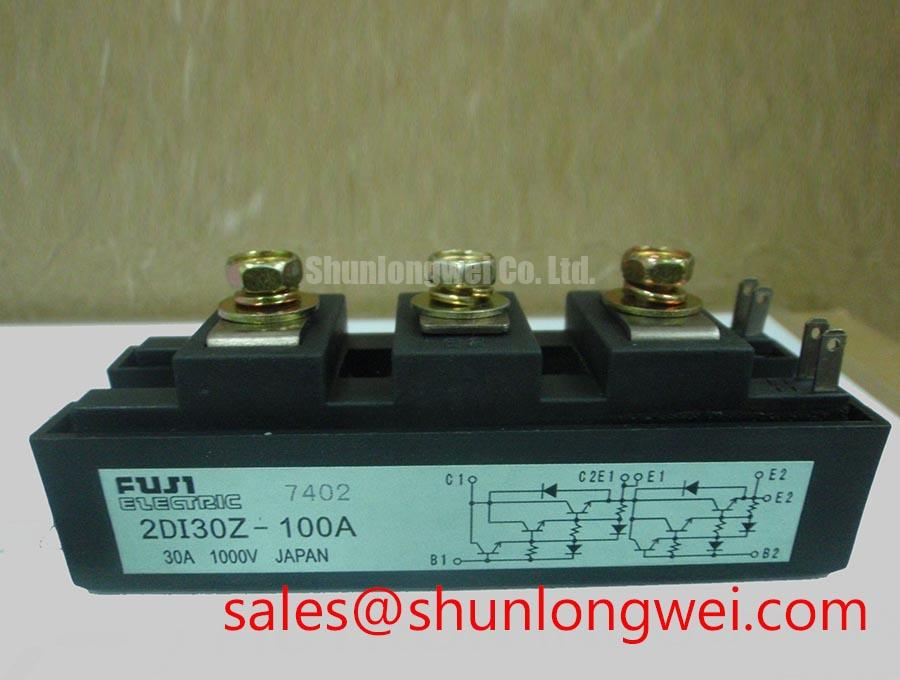
| 2DI150MA 050 | Fuji Electric family reference | Diode module | Review the applicable product data | Confirm mechanical and terminal compatibility |
Field Diagnostics and Commissioning: I2t Sub Cycle Protection in 4R3TI60Y 080 Topologies
During a short circuit review, start with the actual fuse clearing record, not the nominal current printed on the diode. Capture the selected semiconductor fuse class, pre arcing and total clearing I2t data, prospective fault current, DC or AC circuit conditions, and the physical distance between the fuse and protected branch. Then compare those values with the permitted surge and short duration withstand information for the complete diode application.
A dead short can also expose weaknesses in busbar joints, terminal clamping, capacitor discharge paths, and enclosure containment. Inspect the module mounting surface and terminal interfaces after a protection event, and record discoloration, looseness, cracking, or changes in thermal behavior. Do not return the cabinet to service solely because the diode passes a static meter check; the fuse path, insulation condition, snubber parts, and switching waveform require coordinated commissioning.
Where the 4R3TI60Y 080 is considered for an SVC branch or capacitor switching assembly, engineers can use the Power Semiconductor Selection Guide to structure the comparison of current path, protection, thermal interface, and installation constraints. The final acceptance record should identify the installed device, approved fuse coordination, terminal torque procedure, thermal observations, and the measured switching behavior of the completed assembly.