Content last revised on October 16, 2026
Preventing Spurious Faults: Terminal Overheating Checks for 6MBI75S-120
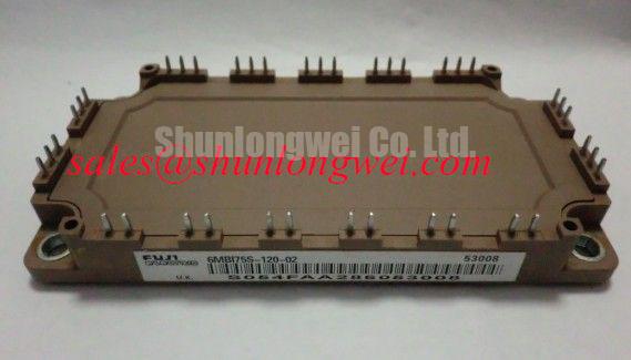
Isolate the power stage, verify that the DC link is discharged, and compare terminal condition before disturbing the connections around the 6MBI75S-120. Photograph the conductor arrangement and gate wiring first: a disturbed connection can hide the original fault or introduce a different one during reassembly. The Fuji Electric module carries a 1200 V collector-emitter voltage rating and a 75 A continuous collector current rating under its specified operating conditions.
For replacement assessment, keep the complete 6MBI75S-120 product identity attached to the maintenance record. Its electrical ratings support initial screening; terminal correspondence, mechanical fit, gate-drive behavior, and cooling conditions determine whether the repair can proceed without changing the original power-stage design.
Measure suspect bolted connections with a four-wire micro-ohmmeter after isolating parallel current paths that could distort the reading. As a Design Consideration, position the sense probes consistently across each joint, document conductor temperature, and compare equivalent connections. A handheld continuity indication cannot resolve the small resistance changes relevant to a loaded power terminal.
Use the equipment manufacturer's joint acceptance criteria rather than imposing a universal micro-ohm limit on this module. Contact resistance depends on the connection geometry, conductor interfaces, surface condition, and measurement arrangement. Inspect mating surfaces for contamination, displaced hardware, damaged threads, and evidence of uneven contact pressure before deciding whether tightening alone is appropriate.
During an authorized energized inspection, compare thermal images at comparable load and cooling conditions. As a Design Consideration, account for surface emissivity and reflections when interpreting apparent terminal temperatures. A localized hot region warrants checking the joint and adjacent conductor; broader heating can also involve current imbalance, restricted cooling, or heat conducted from nearby components. Neither pattern establishes a single cause.
Field Alert: Support the conductors during reassembly and use the specified terminal tightening procedure rather than increasing torque to compensate for a heating joint.
The 600 W power dissipation rating applies under the specified datasheet conditions; it is not a permissible terminal-heating allowance or a prediction of normal operating loss. Keep conductor loading off the module terminals, preserve the original electrical clearances, and inspect the cooling interface separately. An Engineering Recommendation is to retain comparable resistance and thermal records so later inspections can reveal changes without turning an isolated reading into an unsupported pass-or-fail verdict.
Field Diagnostics & Commissioning: Gate Resistance Checks When Replacing 6MBI75S-120
Record the installed turn-on and turn-off gate resistors before changing the module or driver board. As a Design Consideration, compare the driver output stage, gate-loop routing, resistor arrangement, and protection circuitry with the original schematic. A resistor value that worked with another device does not establish suitable switching behavior here.
Official Specifications include a typical 2.30 V collector-emitter saturation voltage, a typical 6.0 V gate-emitter threshold voltage, a 0.35 µs turn-on time, and a 0.45 µs turn-off time. These characteristics belong to their datasheet measurement conditions. Threshold voltage is not a full-enhancement drive setting, and the stated switching times are not controller dead-time prescriptions.
As a Design Consideration, assess gate-emitter and collector-emitter waveforms with suitable isolated or differential instrumentation during controlled commissioning. Gate resistance influences switching loss, current slew rate, overshoot, and ringing. The Miller interval reflects gate charge transferred while collector-emitter voltage changes; reverse-transfer capacitance contributes to this coupling but is not itself a charge quantity. Evaluate active Miller clamping or voltage-clamping behavior only where the actual driver includes those functions.
For desaturation protection, review blanking, detection, propagation delay, and shutdown behavior together. An Engineering Recommendation is to validate the complete fault response against the module's documented short-circuit limits and the actual driver circuit, rather than adopting a universal response time. Where two-stage soft turn-off is implemented, verify that its initial and final discharge phases limit overshoot without extending fault stress excessively.
During parts comparison, 6MBI20GS-060 is a separate device requiring its own electrical and mechanical assessment, not an established drop-in replacement. Match the complete ratings, connection diagram, package drawing, and protection requirements before approving any substitution.
Transient Dynamics & Electrical Design: Bi-Directional DC-DC Buck-Boost Conversion on 6MBI75S-120
Trace the intended charging and discharging paths on the converter schematic before treating the module as a bidirectional conversion solution. As a Design Consideration, identify controlled current paths, diode conduction intervals, precharge behavior, and the switching states used during power reversal. Bidirectional energy transfer does not, by itself, establish four-quadrant voltage and current capability.
Commercial string inverter and micro-grid energy-storage equipment are potential compatibility-assessment contexts, subject to the original circuit and cooling design. When evaluating this module in an associated DC conversion stage, designers should check battery operating range, link-voltage excursions, reverse-current conditions, and shutdown behavior. Those system requirements cannot be inferred from the module's voltage and current labels alone.
As a Design Consideration, minimize the commutation-loop area and preserve the intended relationship between the DC-link capacitor and switching terminals. Closely coupled bus conductors can reduce stray inductance when their geometry and insulation are appropriate. Verify turn-off peaks at the module terminals under representative operating transitions, including power reversal; a remote bus-voltage measurement can miss local overshoot.
Repeated charging and discharging can change semiconductor losses and cooling demand. An Engineering Recommendation is to evaluate the actual load sequence with the applicable thermal impedance data rather than infer junction temperature directly from a single case-temperature reading. If devices are paralleled, assess static conduction sharing and dynamic switching sharing separately; positive temperature-coefficient behavior must not be assumed across every operating point.
The broader discussion in Unlocking Efficiency in Industrial Drives provides technology context, not Fuji-specific acceptance limits. Likewise, upstream phase-controlled rectifier harmonics and semiconductor fuse coordination remain system matters: assess conduction-angle effects at the input stage, and coordinate fuse clearing energy with the protected circuit rather than assuming a fast fuse prevents module damage during a hard short circuit.
6MBI75S-120 Insulation Checks: Terminal-to-Baseplate Testing
Disconnect sensitive connected electronics and establish the approved test connection before evaluating terminal-to-baseplate insulation. The 2500 V AC isolation voltage for 1 minute is an Official Specification. It does not establish an equivalent DC megohmmeter setting, an insulation-resistance acceptance threshold, or permission to repeat a production withstand test during routine maintenance.
As a Design Consideration, distinguish insulation-resistance measurement from dielectric-withstand testing. The former measures leakage behavior under a defined test arrangement; the latter applies a specified electrical stress under controlled conditions. Use the equipment maintenance procedure and applicable module instructions to select the method, terminal grouping, test duration, and post-test discharge process.
Clean accessible insulating surfaces using the approved service method, then inspect for conductive residue, tracking, cracks, and damaged barriers. Dust mixed with moisture can alter surface leakage, but an insulation reading does not independently establish the integrity or material composition of the internal substrate. Preserve external creepage paths and clearance around terminal hardware without assigning an unsupported universal spacing.
The Fuji Electric Europe Semiconductor & Power Electronics resources provide manufacturer technical context. Fuji's semiconductor and SiC product resources concern separate device families; their characteristics should not be transferred to this IGBT module.
An Engineering Recommendation is to record the insulation test arrangement, ambient conditions, instrument identification, and result alongside the repair record. After testing, discharge the tested assembly through the approved procedure, restore the protective connections, and inspect the baseplate seating and thermal interface. Recommission only after the electrical isolation checks and mechanical reassembly meet the equipment's service requirements.