
Content last revised on October 24, 2026
6MBP50RA120 Replacement Assessment and Specifications
- Isolate the equipment, verify DC-link discharge, and compare cold-state resistance readings between corresponding power terminals with the control connections disconnected as specified by the equipment service procedure.
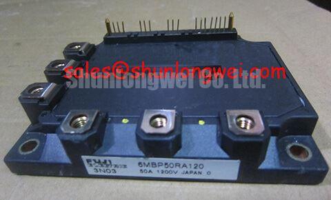
- Check the 6MBP50RA120 marking against the original assembly record, then inspect terminal alignment, mounting surfaces, and connector engagement.
- Trace auxiliary supply and control-return connections on the actual schematic before attaching test instruments or reconnecting the driver interface.
- Inspect the heatsink contact area and existing thermal interface for contamination, uneven compression, or evidence of disturbed mounting.
The Fuji Electric 6MBP50RA120 is a 1200 V, 50 A IPM module. During replacement assessment, match its electrical ratings with the installed assembly’s control interface, terminal arrangement, and cooling requirements. A resistance comparison can identify an abnormal branch for further investigation, but surrounding capacitors, diodes, and connected circuitry can influence readings; isolate the relevant paths before drawing a component-level conclusion.
| Parameter | Official Specification |
|---|---|
| Collector-emitter voltage, VCES | 1200 V; absolute maximum rating at case temperature 25 °C |
| Continuous collector current, IC | 50 A; absolute maximum rating at case temperature 25 °C |
| Pulsed collector current, ICP | 100 A for 1 ms |
| Maximum power dissipation, PC | 400 W per transistor at case temperature 25 °C |
| Collector-emitter saturation voltage, VCE(sat) | 2.6 V typical; 3.3 V maximum at collector current 50 A and junction temperature 25 °C |
| Turn-on time, ton | 0.80 µs typical at junction temperature 25 °C; retain the datasheet switching-test conditions when comparing results |
| Turn-off time, toff | 1.80 µs typical at junction temperature 25 °C; retain the datasheet switching-test conditions when comparing results |
| Overheating protection | Integrated overheating detection |
| Isolation voltage, Viso | 2500 V AC for 1 minute; component test specification |
The power-dissipation rating assumes the stated case temperature; it is not an available continuous heat budget for an assembled cabinet. Interface supply limits, terminal assignments, mechanical dimensions, protection timing, and mounting requirements belong in the datasheet and equipment drawing used for the replacement assessment.
6MBP50RA120 Thermal-Electrical Optimization: Active Miller Clamp Implementation Practical Tuning
Trace the module’s control interface before considering any active Miller clamp modification. Design Consideration: a clamp acts on an accessible gate-drive node, whereas an IPM presents an integrated control boundary. An external clamp or negative gate supply should therefore enter the repair plan only where the manufacturer’s interface documentation explicitly supports that connection. Neither feature should be inferred from the module’s voltage and current ratings.
During a complementary switching transition, collector-voltage movement can couple charge into the opposite device’s gate circuit. Excessive gate-loop impedance can allow the resulting disturbance to increase unintended conduction. Where the documented driver architecture includes a clamp, assess its local return path, connection integrity, and activation relative to the switching event. The relevant question is whether the gate remains controlled throughout the disturbance, rather than whether a clamp component is present on the board.
For field troubleshooting, correlate control-input activity, auxiliary supply stability, phase-node transitions, and protection outputs using appropriately rated isolated measurement equipment. A narrow pulse observed at a controller connector does not establish the internal gate waveform. Probe pickup and return-path movement can produce similar traces, so repeat the observation with a controlled probe arrangement before attributing it to cross-conduction.
Engineering Recommendation: preserve separation between noisy power conductors and low-level control wiring, keep documented driver-return paths compact, and inspect connector routing against the original layout. Clearance requirements follow working voltage, insulation coordination, and the equipment construction; they should not be reduced to an invented spacing rule for this module. Negative gate bias is likewise a driver-specific design decision, with its magnitude determined by supported gate limits and switching validation.
For device-family context, Fuji Electric’s power semiconductor technology resources provide manufacturer information. The Fuji Electric discrete IGBT resources concern a separate device category; discrete gate-drive arrangements should not be transferred directly to the 6MBP50RA120 interface.
6MBP50RA120 Thermal-Electrical Optimization: Thermal Stress Alleviation in Bidirectional Power Flow Practical Tuning
Separate real-power reversal from reactive-current loading when reviewing thermal behavior. Design Consideration: changing power direction changes conduction paths and switching intervals, while reactive current can continue heating the bridge without an equivalent increase in delivered real power. Evaluate phase current, modulation state, DC-link behavior, and heatsink temperature together rather than using the sign of power flow as a thermal indicator.
When assessing compatibility with a commercial string inverter or micro-grid energy-storage converter, designers should verify the complete topology, control interface, and cooling arrangement. Four-quadrant operation belongs to the converter and its controls; the module’s 1200 V and 50 A ratings alone do not establish that system capability. Battery charge-rate commands also require translation through the converter’s actual voltage, current, and duty profile before semiconductor loading can be assessed.
Phase-angle and modulation changes redistribute conduction between switching devices and freewheeling paths. Inspect temperature behavior through representative transitions in power direction, including periods where current remains substantial near low real-power output. DC-link ripple should be assessed at the bridge connections as well as at the capacitor bank. Connection impedance can make these observations differ, and ripple smoothing remains a system-level capacitor and control decision.
Where an RC snubber is fitted, inspect its connections and component condition before altering the network. Its damping and dissipation depend on measured ringing, switching conditions, and the surrounding parasitic circuit. An oversized or poorly placed network can add heat without adequately controlling the transient. The related 6MBP200VEA060-50 should be evaluated by its own topology and ratings if it appears in an associated converter stage; its part number does not establish suitability as an upstream rectifier.
At the mechanical interface, remove old thermal compound without damaging the mating surfaces, inspect flatness and seating, and apply the specified interface material using the documented assembly method. Excess compound cannot correct a distorted mounting surface. Field Alert: Follow the module’s specified tightening sequence and torque, and maintain uniform thermal-interface coverage rather than compensating for poor seating by overtightening.
The article Unlocking Efficiency in Industrial Drives offers separate technology context; it does not establish the 6MBP50RA120’s chip generation or service life. For this repair, retain comparable load and temperature records to judge whether the restored thermal path behaves consistently.
6MBP50RA120 Thermal-Electrical Optimization: Separating Driver Return from Main Current Practical Tuning
Identify control returns from the terminal drawing instead of treating every emitter-related connection as interchangeable. Design Consideration: shared impedance between a high-current path and a control reference can introduce a transient voltage during current change. That disturbance can shift the apparent input level or interfere with fault signaling even when the controller output itself remains stable.
A dedicated Kelvin emitter connection must be explicitly identified in the module documentation before it is used. The confirmed specifications above do not establish such a terminal on the 6MBP50RA120. Keep the documented signal reference distinct from load-current routing, and preserve the original interface connections rather than creating an assumed auxiliary emitter connection during repair.
Compare the control signal at its source with the signal measured relative to the module’s designated input reference. If discrepancies coincide with power switching, inspect return continuity, connector contact condition, and routing near the power loop. This comparison helps distinguish a controller-command problem from reference movement. It also avoids treating a noisy measurement at a remote ground point as proof of an internal switching fault.
Replacement comparisons require the same attention to interface details. The related 6MBP50RA060 should not be described as a verified direct replacement for the 6MBP50RA120: similarity in naming does not establish equal blocking voltage, terminal mapping, or protection behavior. Record those differences alongside mechanical fit before considering any change to the installed assembly.
Engineering Recommendation: if multiple modules share current in the existing design, inspect both power-path symmetry and control timing. Static current sharing and switching current sharing involve different influences, including temperature, connection impedance, and propagation differences. Do not assume that a favorable temperature coefficient guarantees balanced operation. Compare branch currents under the equipment’s approved test conditions and investigate uneven heating alongside those measurements.
Field Diagnostics & Commissioning: Driver Power Stage Start-Up Inrush Mitigation in 6MBP50RA120 Topologies
Hold switching commands inactive while checking auxiliary-supply startup, reset behavior, and the equipment’s DC-link enable sequence. Engineering Recommendation: verify that the documented supply-ready and protection interlocks reach valid states before the controller permits power switching. Negative turn-off bias is not a universal IPM startup requirement; assess the actual interface supply and undervoltage behavior specified for the installed circuit.
Capture the auxiliary rail through startup and shutdown rather than checking only its settled voltage. A supply can appear correct on a meter while briefly collapsing as local capacitors charge or control circuits become active. Compare the rail, enable command, and fault response on the same time reference. Investigate unexpected pulses or repeated resets before proceeding to the equipment’s controlled power-stage test.
Where the external supply architecture includes bootstrap circuitry, evaluate capacitor recharge opportunities across the intended switching pattern and inspect the charging diode’s behavior against the circuit requirements. Bootstrap capacitance, diode recovery, and charge demand are system-design matters, not established features of the 6MBP50RA120. A long high-side command interval can change recharge conditions, so startup success alone does not verify sustained operation.
Keep driver-supply charging and DC-link precharge as separate diagnostic paths. Check the existing precharge circuit, contactor sequence, and bus-voltage feedback before enabling the bridge. During energy return, verify the documented destination for that energy; where fitted, the braking chopper and resistor require their own control, continuity, and thermal checks. The IPM’s integrated overheating detection does not supervise the braking resistor.
During the approved commissioning run, observe phase-current symmetry, DC-link excursions, auxiliary-rail stability, and protection signaling as load changes. Retain the first fault event and its preceding waveforms before resetting the controller. If a trip repeats, reproduce it only within the equipment’s service procedure and use the captured sequence to distinguish supply collapse, control-reference disturbance, and excessive power-stage loading.