Content last revised on September 28, 2026
Transient Dynamics & Electrical Design: Turn-Off Voltage Stress on 6MBP50TEA120
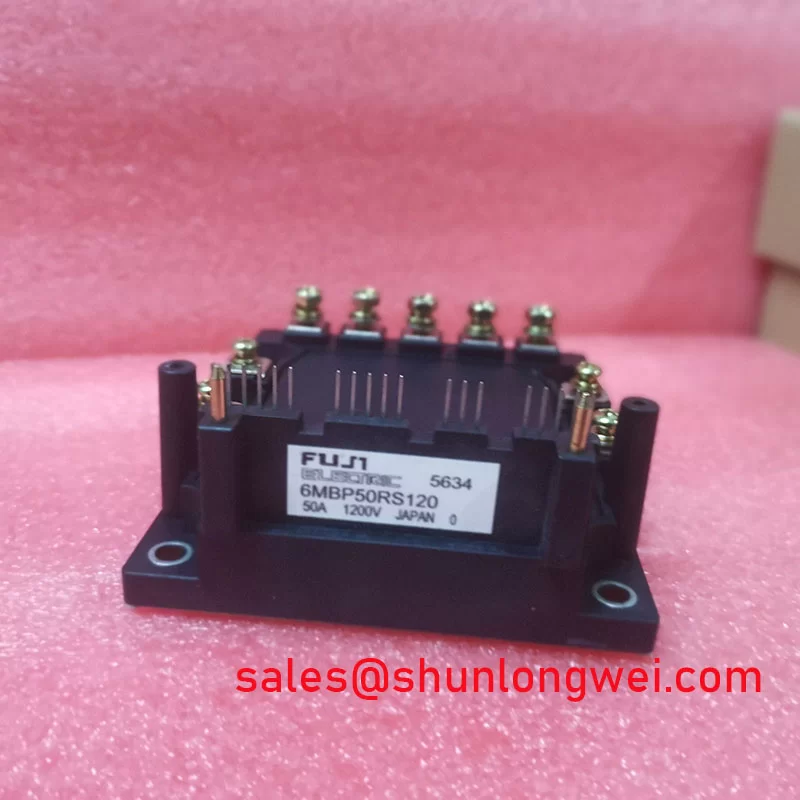
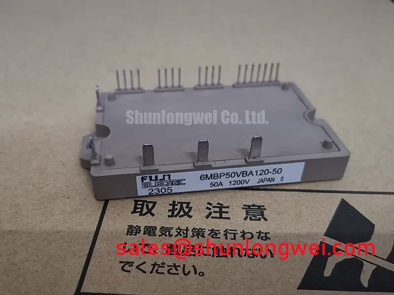
With the DC link isolated and discharged, compare the terminal markings and cold-state measurements of the removed unit with the equipment service documentation before evaluating 6MBP50TEA120 as a replacement. Fuji Electric identifies this part as an IPM Module with a 1200 V voltage rating and a 50 A current rating, each an Official Specification. Those ratings establish necessary electrical boundaries; they do not, by themselves, establish connector, control, thermal, or mounting compatibility.
A technician investigating a failed inverter should first record the DC-link voltage and switching waveform under controlled operating conditions. At turn-off, current changing through stray inductance can raise the voltage at a power device above the DC-link level. This is a Design Consideration, not an additional voltage rating for the module. The measured peak, including ringing, must be evaluated against the 1200 V Official Specification under the equipment’s relevant operating conditions.
Inspect the busbar joints, DC-link capacitor connections, and physical return path before changing a snubber. Loose or extended connections can increase loop inductance; a damaged or disconnected snubber can alter the waveform. Use a measurement method rated for the circuit and capture switching events at the module terminals where safely practicable. A trace taken elsewhere in the cabinet may miss local overshoot. If the peak is excessive, the system designer should assess loop geometry and snubber performance, then verify the result during switching tests rather than select a capacitor from the module’s voltage rating alone.
Long motor cables warrant a separate check. Reflected waves can make the voltage at motor terminals differ substantially from the waveform measured at the inverter. Cable length, rise time, termination, and any output filter determine the result in the installed system. For an electric forklift or other material-handling drive being assessed for compatibility, record both the inverter-side and motor-side conditions before attributing insulation stress to 6MBP50TEA120.
The nearby 7MBR50SB120-01 is a useful reference in a purchasing comparison, not an assumed drop-in replacement. Compare the original equipment documentation for terminal arrangement, control interface, mechanical fit, and operating ratings before considering either part. Fuji Electric’s power module product portal provides manufacturer context for checking the appropriate module documentation.
6MBP50TEA120 Circuit Protection & Reliability: Assessing Transient Thermal Response
After an overload trip, examine the load-current record and cooling condition before treating the 50 A Official Specification as a permissible value for every pulse. Junction temperature depends on losses over time and on heat transfer through the installed assembly. A brief event and a sustained overload can produce different thermal responses even when the current peaks appear similar. Determining a permissible pulse requires the applicable manufacturer thermal data, the switching conditions, and the equipment’s protection settings; no transient thermal impedance curve is established by the ratings given here.
On the bench, check whether a trip follows acceleration, braking, a change in switching behavior, or a loss of airflow. Inspect the heatsink for dust buildup and verify that the fan and air path operate as intended. Review the contact surface and thermal-interface material during scheduled maintenance, following the equipment maker’s instructions for cleaning and reassembly. These observations help distinguish a cooling problem from an electrical overload without assigning a single cause to the symptom.
Maintenance note: Isolate and discharge the DC link before touching module terminals or disturbing the heatsink assembly.
For a pulsed-duty assessment, the system engineer should use the applicable transient thermal impedance information to estimate junction-temperature rise from the measured loss profile, then check the result against the manufacturer’s temperature limits. Switching frequency, ambient temperature, and airflow affect that assessment, but a universal derating schedule would not be an Official Specification for 6MBP50TEA120. In a cold or humid installation, also inspect the enclosure for condensation and confirm that its environmental controls are working before energizing the drive.
Reliability discussions should stay tied to the installation and available evidence. Altitude, insulation coordination, and device failure-rate questions require relevant manufacturer and system-level data; the 1200 V rating alone does not quantify those outcomes. Fuji Electric’s Power Semiconductor and IPM Modules information is a starting point for locating manufacturer guidance, while the equipment documentation governs the assembled drive’s limits.
Benchtop Waveform Tuning: Gate-Impedance and Switching-Stress Checks for 6MBP50TEA120
When a repaired inverter shows abnormal switching, compare its command signals, supply rails, fault output, and measured power waveform with a known-good channel or the equipment service procedure. Do not assume that a gate-drive arrangement used with another module applies to 6MBP50TEA120. The supplied specifications confirm its IPM Module category but do not establish an external gate-terminal configuration or a permissible gate-bias value.
High switching slew rates can couple noise into control wiring and measurement references. As a Design Consideration, keep the driver and sensing return paths consistent with the original layout, check connector seating, and inspect shielding and grounding for changes made during repair. If a scope trace suggests unintended turn-on or cross-conduction, verify probe placement and reference integrity before altering drive components. Any clamp circuit, gate-impedance change, or bias adjustment must be supported by the specific module documentation and validated in the complete drive.
Inspect the freewheeling current path and associated waveforms as part of that diagnosis, without presuming an undocumented internal diode arrangement. Reverse-recovery behavior, where applicable to the circuit, can contribute to switching stress and electrical noise. Comparing current transitions and voltage ringing across operating conditions is more useful than assigning an EMI or diode diagnosis from a single trace. The assembled equipment, rather than an individual module, is the subject of any EMC compliance assessment.
Another module listed for related topology evaluation is 7MBR50SA120-50. Its presence in a sourcing comparison does not establish that its supply, control, or protection connections match this unit. For background on how power-stage topology affects switching behavior, see Resonant Topologies in Home Appliances; apply any principles from that discussion only where they match the actual equipment circuit.
Field Diagnostics & Commissioning: Control-Return Routing in 6MBP50TEA120 Topologies
Before reconnecting control wiring, trace each conductor against the original schematic and the terminal identification on the removed assembly. Do not infer an auxiliary Kelvin-emitter terminal from the module category or model name. If the documented system provides a separate sensing or control return, preserve its intended routing rather than combining it with a high-current return at an arbitrary point. The reason is practical: voltage developed along a shared current path can disturb the control reference during switching.
At commissioning, check terminal tightness using the equipment maker’s instructions, confirm connector engagement, and review the first controlled run for unexpected fault indications or waveform changes. If oscillation appears, compare the control reference and power waveform with the documented signal path; also inspect the busbar, cable routing, and probe setup. Oscillation can have several contributors, so a changed trace should prompt measurement and comparison, not an automatic gate-circuit modification.
For a forklift traction-inverter repair, complete the compatibility check with the original assembly’s mounting pattern, connector assignment, cooling interface, and protection behavior. The confirmed product facts for 6MBP50TEA120 remain its Fuji Electric IPM Module identity, 1200 V Official Specification, and 50 A Official Specification. Release the equipment only after its own service procedure and operating tests support the installation.