Content last revised on October 10, 2026
CM600HB-90H Main Terminal Alignment and Electrical Integration
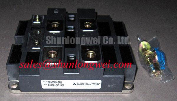
Before energizing a replacement assembly, inspect the main terminal faces, confirm that the busbar sits naturally against the module terminals, and check that the fastener does not pull the copper connection sideways. The CM600HB-90H is a Mitsubishi Electric IGBT module with a collector-emitter voltage rating of 4500 V and a collector current rating of 600 A under the specified datasheet conditions. These values identify the product class; they do not replace the switching, thermal, and insulation checks required by the complete inverter design.
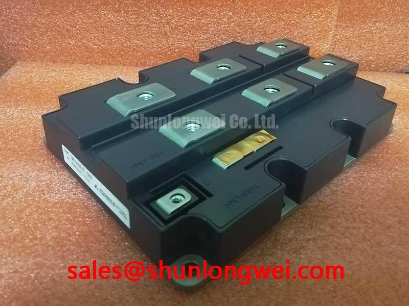
During installation, align the laminated busbar or flexible copper link before tightening any terminal hardware. A screw that enters at an angle can create a levering force on the internal terminal structure, especially when the cabinet experiences vibration or repeated thermal expansion. Check thread engagement, washer seating, and the flatness of the mating conductor. The terminal should be clamped by the intended hardware rather than used to draw a misaligned busbar into position.
Keep the high-current path compact and symmetrical where parallel switching paths are used. The gate return path should remain separate from the power-current path, with its routing controlled by the gate-driver layout rather than by the shortest available cabinet route. Designers evaluating the CM600HB-90H against another high-power module can use CPT600150A as a separate comparison reference, but mechanical dimensions, terminal positions, electrical ratings, and driver requirements must be compared line by line before any substitution is considered.
For a utility-scale 1500 V central photovoltaic inverter, verify the actual DC-link arrangement, switching sequence, isolation coordination, and fault-clearing strategy at system level. The module’s 4500 V rating is an official device specification, while allowable operating voltage in the finished inverter is determined by switching overshoot, insulation coordination, temperature, protection response, and the equipment certification plan.
| Evaluation point | CM600HB-90H | CPT600150A reference device |
|---|---|---|
| Manufacturer | Mitsubishi Electric | Verify from the applicable datasheet |
| Collector-emitter voltage rating | 4500 V | Verify from the applicable datasheet |
| Collector current rating | 600 A under the specified datasheet conditions | Verify from the applicable datasheet |
| Package designation | Module | Verify mechanical compatibility |
Thermal Feedback, Gate Symmetry, and Protection Coordination
Check the temperature coefficient of the IGBT’s steady-state saturation voltage at the intended operating current when assessing static current sharing between parallel paths. A positive coefficient can help reduce current imbalance under suitable operating conditions, but dynamic sharing is governed by gate-loop inductance, driver timing, stray inductance, device temperature, and the physical symmetry of the power circuit.
Match the gate wiring length and return geometry for each parallel device position. A Kelvin-style emitter return, when provided by the actual module and driver topology, should not be merged with a high-current emitter route at an uncontrolled point. The driver should be checked for unequal turn-on and turn-off behavior by comparing gate-to-emitter waveforms at the module terminals, not only at the driver output connector.
Short-circuit protection should combine desaturation or equivalent collector-emitter monitoring with a controlled turn-off sequence. A protection architecture may use a rapid detection target below 3 µs where the selected driver, sensing circuit, blanking interval, and device short-circuit withstand data support that choice. This is an engineering design target, not an official CM600HB-90H product rating. A protection sequence may first limit gate drive, followed by a controlled soft turn-off that reduces the risk of excessive collector-emitter overshoot.
A two-stage soft turn-off arrangement should be tuned against the actual DC-link voltage, gate resistance, driver current capability, wiring inductance, and fault current. Excessively abrupt turn-off can increase voltage overshoot, while an overly slow response can increase short-circuit energy. Capture the collector-emitter voltage and gate-emitter voltage simultaneously during controlled commissioning tests, then verify that the protection circuit reaches its intended state without producing a secondary gate pulse.
The device should not be treated as a complete protection system. A rectifier or front-end topology may include a separate power component such as MPKB2CA150U60 if its ratings and configuration suit the design, but the electrical relationship between the rectifier, DC-link capacitor, precharge path, inverter bridge, and gate driver must be established from the system schematic.
⚠️ Maintenance Note: Monitor contact temperature during scheduled service and clean the heatsink airflow path before thermal readings are compared with earlier maintenance records.
Commissioning Common-Mode Transient Immunity in CM600HB-90H Topologies
Commissioning should begin with the isolation barrier and the physical separation of control, gate, and power-current routes. Isolation withstand voltage, reinforced insulation requirements, and common-mode transient immunity belong to the selected gate-driver and isolation architecture, not to the module’s voltage and current ratings. A withstand test rating above 5 kV or a common-mode transient immunity target above 100 kV/µs may be considered where supported by the design requirements, but neither alone establishes suitable reinforced insulation. Confirm the test conditions, working-voltage ratings, and applicable insulation requirements from the driver documentation and system insulation design before applying them to a 4500 V-rated switching device.
Common-mode disturbances can couple through the gate-driver transformer or isolator capacitance, heatsink structure, control cable shield, and measurement equipment. Keep the isolated gate loop compact, avoid routing sensitive control traces beside high di/dt collector paths, and provide a deliberate return path for displacement current. During commissioning, use suitably rated differential probes and confirm that the measurement setup itself is not creating a false gate pulse.
A spurious gate trigger may appear as a narrow disturbance at the module gate terminal, an unexpected collector-current notch, or an unequal switching edge between parallel paths. These symptoms require correlation between the driver output, gate-emitter voltage, collector-emitter voltage, and isolated controller command. Compare the suspect channel with a known-good channel under the same switching condition rather than assigning a single cause from one waveform.
The isolation barrier should also be evaluated after the cabinet reaches its normal humidity and temperature condition. Condensation, contamination, cable stress, and damaged insulating surfaces can change the effective creepage and clearance environment. The system integrator should verify the required isolation test method, working voltage, pollution assumptions, and enclosure conditions within the applicable equipment standard.
Thermal packaging influences electrical stability because junction temperature changes switching behavior and protection thresholds. The thermal design principles discussed by Electronic Design are useful when reviewing safe operating area and heat-flow paths. Where ceramic substrate construction is part of the selected module technology, the general thermal-shock background of silicon nitride ceramic substrates can inform packaging discussions, but it should not be treated as a confirmed internal construction detail for this model.
Baseplate Flatness, Thermal Interface Control, and Sequential Fastening
Thermal installation begins with a clean heatsink surface and a baseplate that is supported across its intended mounting area. Remove old interface material without scoring the heatsink, then inspect for burrs, trapped particles, and local distortion around mounting holes. A practical engineering recommendation is to control the applied thermal interface layer within the selected material supplier’s process window; a nominal working range of 50 to 100 µm may be used only when it matches the compound, surface finish, and application method.
Do not use mounting screws to correct a visibly bowed heatsink or to force a tilted module into contact. Place the module in its natural position, start all fasteners by hand, and tighten them progressively in a crosswise sequence. The final torque must come from the Mitsubishi Electric mechanical documentation or the approved assembly specification for the exact hardware. Generic torque values are not official CM600HB-90H ratings.
Void reduction depends on controlled compound application, surface preparation, module placement, and the pressure profile created during fastening. After assembly, inspect the contact pattern where the maintenance process permits it, and compare thermal readings across the baseplate during a stable load condition. A local hot region can result from interface nonuniformity, airflow imbalance, terminal resistance, sensor placement, or unequal semiconductor loading, so the service record should capture all of these observations.
Temperature cycling also changes the condition of the interface. During preventive maintenance, check for dried or displaced compound, loosened hardware, discoloration around the power terminals, and dust accumulation that restricts heatsink airflow. In humid industrial cabinets, inspect for condensation marks and confirm that enclosure heating, ventilation, and drainage arrangements are functioning before the next high-power run.
When the module is evaluated for a utility-scale central photovoltaic inverter, the complete thermal path includes the semiconductor junction, internal package interfaces, baseplate, thermal interface material, heatsink, airflow or liquid circuit, and cabinet environment. Review each boundary independently and record temperatures at repeatable operating points. The broader application considerations in Industrial Applications can support system-level planning, while final acceptance remains dependent on the equipment designer’s measured electrical and thermal margins.