

Content last revised on September 22, 2026
CM75E3Y-24E Operational Boundaries: Evaluating Negative Gate Bias vs Active Miller Clamp Limits
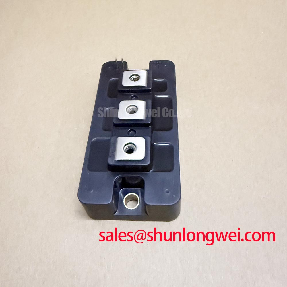
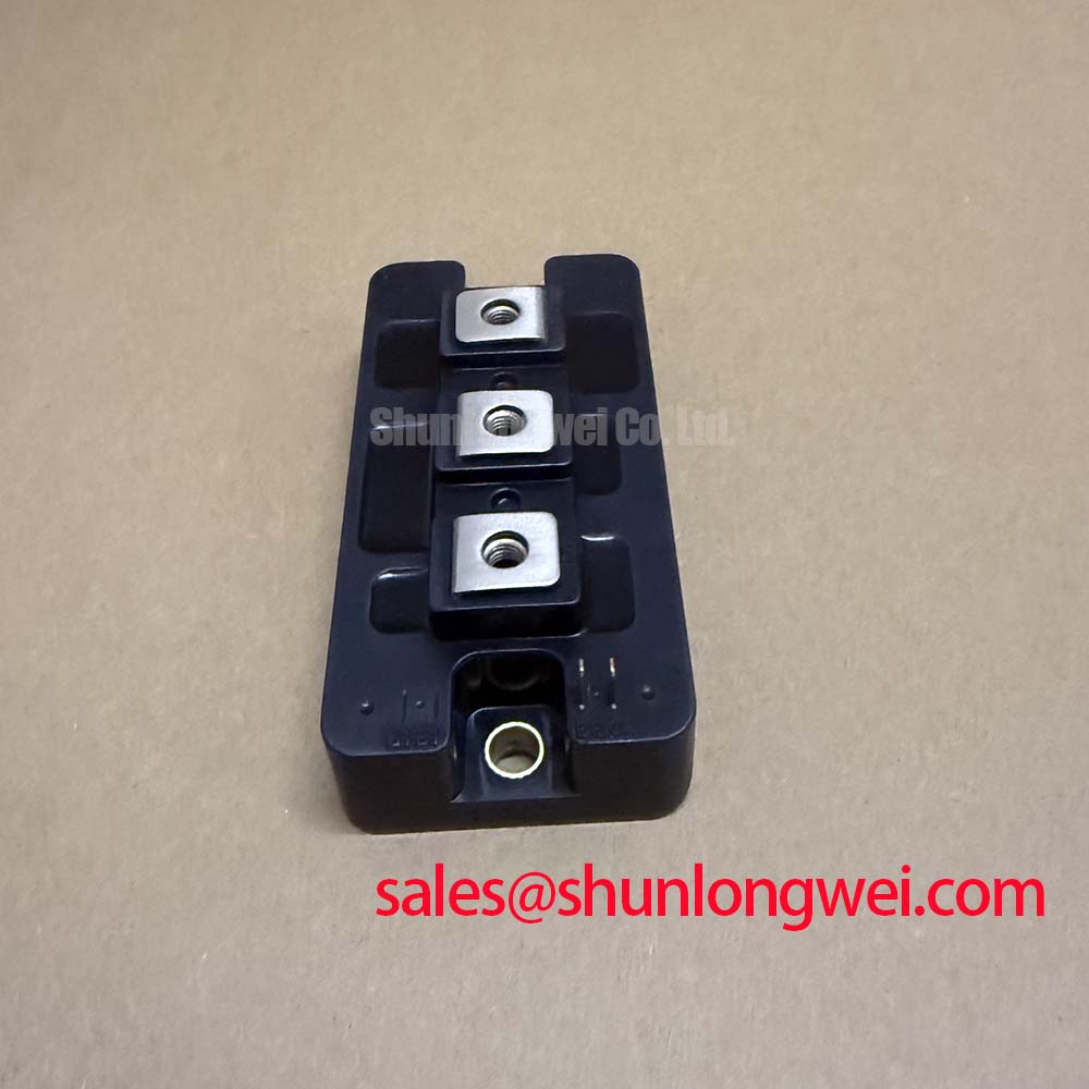
With power removed and the DC link safely discharged, first inspect the CM75E3Y-24E terminal area for loosened hardware, heat discoloration, cracked insulation, or conductive debris before comparing cold resistance paths with the removed unit and the documented inverter circuit.
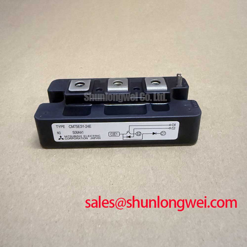
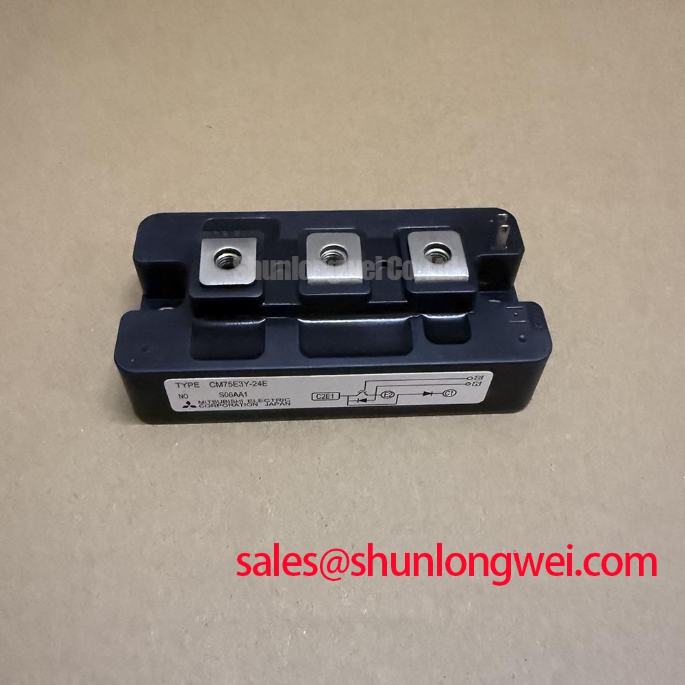
The CM75E3Y-24E is a Mitsubishi Electric IGBT module with a specified 1200V voltage rating and 75A collector-current rating under the applicable datasheet conditions, in a module package. These are Official Datasheet Specifications and establish the electrical identity that must be matched before any repair or replacement assessment. They do not, by themselves, confirm terminal arrangement, gate drive requirements, switching behavior, insulation coordination, mechanical dimensions, or compatibility with a particular controller board.
| Parameter | Official Specification |
|---|---|
| Manufacturer | Mitsubishi Electric |
| Part number | CM75E3Y-24E |
| Collector-emitter voltage rating | 1200V |
| Collector-current rating | 75A under applicable datasheet conditions |
| Package style | Module |
For inverter repairs in electric material handling equipment or forklift traction systems, technicians should treat the original schematic, busbar arrangement, driver board markings, and heatsink interface as the primary compatibility references. A voltage and current rating match is necessary, but it is not a complete interchangeability decision.
Before reconnecting a replacement module, inspect the gate driver output path from the driver IC through its gate resistor network to the module control terminals. Check for lifted pads, damaged plug contacts, carbon tracking, and unequal wiring lengths between switching positions. A module can be electrically intact while a damaged gate path causes irregular switching after energization.
Negative gate bias and active Miller clamp functions address a system level concern: a rapid collector voltage transition can capacitively couple into a gate circuit and raise the gate potential of a device intended to remain off. If the off state gate path has excessive impedance, unwanted conduction can occur. The result may appear as abnormal DC link current, distorted phase current, gate waveform ringing, or repeated protection trips. These observations do not isolate one cause; they should be evaluated with the inverter schematic and measured waveforms.
The specified 1200V rating defines the module voltage class, while the permissible gate drive range, gate threshold behavior, and switching conditions must be verified against the applicable Mitsubishi Electric documentation for this exact part number. Do not impose a negative gate voltage solely because another inverter uses one. It is an Engineering Recommendation to examine the original driver supply rails, the driver IC data, isolation barrier condition, and controller timing before reproducing the gate drive arrangement.
An active Miller clamp can provide a low impedance discharge route near the gate drive output during the off command. Whether it is appropriate depends on the installed driver topology, isolated supply arrangement, switching transients, and measured gate voltage. When investigating a suspected false turn on event, capture the gate to emitter waveform and collector related switching waveform using measurement practices suitable for the inverter voltage environment. Compare corresponding switching positions under controlled conditions rather than judging a waveform from one leg in isolation.
Clearance and creepage around power and control terminals are assembly conditions, not optional visual details. Remove conductive dust, moisture residue, displaced sealant, and loose wire strands. The system integrator should verify spacing against the actual working voltage, pollution environment, enclosure condition, and applicable equipment standard. No independent EMC, insulation certification, altitude capability, or surge performance claim should be inferred from the module’s voltage rating alone.
⚠️ Field Alert: Never reconnect gate or power wiring until stored energy is discharged and the original terminal map has been checked against the controller documentation.
For a repair evaluation where another 1200V class module is being reviewed, BSM75GD120DLC can be documented as a separate candidate for engineering comparison, but its pinout, mounting geometry, gate requirements, diode behavior, and operating limits must be verified by the system engineer before any substitution is attempted.
CM75E3Y-24E Circuit Protection & Reliability: Calibrating Symmetrical Busbar Geometry for High Current
At a rated current of 75A, the practical current path includes far more than the module terminals. Busbars, laminated conductors, fasteners, capacitor connections, current sensors, fuse links, and return paths all shape the electrical result. During a repair, look for unequal conductor lengths, heat marked joints, misaligned busbar faces, and signs that a copper strap was forced into position under mechanical stress. Such details can alter current distribution and switching overshoot.
IGBT conduction behavior can show a positive temperature coefficient in relevant operating regions, which is a useful Design Consideration when evaluating static sharing between parallel current paths. It does not guarantee equal dynamic switching. Turn on and turn off behavior are affected by driver impedance, gate wiring inductance, layout symmetry, temperature, and timing. Parallel arrangements should therefore be validated under controlled system tests rather than assumed to share current evenly from matching part numbers alone.
Symmetrical busbar geometry is intended to keep commutation paths comparable between corresponding inverter positions. Keep outgoing and return conductors closely coupled where the topology permits, avoid unnecessary loop area, and ensure each gate circuit references the intended local emitter connection specified by the original design. The purpose is to reduce parasitic inductance that can add voltage overshoot during switching. The system engineer must verify peak voltage margins against the DC link voltage using switching tests on the completed assembly.
Freewheeling behavior is also a circuit level issue. Reverse recovery from an inverter’s diode path can contribute to current transients, ringing, and radiated noise. Snubber components, if present in the original equipment, should be inspected for damaged capacitors, poor solder joints, fractured connections, and changed component values. Removing or changing a suppression network without waveform evidence can move stress to another part of the power stage.
In equipment using a front end rectifier or associated power conversion stage, the condition of the DC link supply affects inverter troubleshooting. The BSM75GB120DN2 may be reviewed as a separate component in a related rectifier or complementary power stage assessment, subject to verification of its exact circuit function and connection requirements. Input harmonic behavior, conduction angle, and capacitor ripple are determined by the full converter design, supply source, loading profile, and control method; they cannot be assigned to the CM75E3Y-24E alone.
For broader troubleshooting practices covering electrical measurement, mechanical checks, and evidence based fault isolation, consult the Field Engineer’s Handbook. It is useful when a fault has affected more than one element of the gate drive, power path, or thermal stack.
CM75E3Y-24E Thermal Electrical Optimization: DC Link Capacitance Bank Layout and Low ESR Practical Tuning
Inspect the DC link capacitor bank before applying power to a traction inverter. Confirm that capacitor terminals, busbar joints, precharge connections, discharge paths, and sensing leads are secure and correctly routed. A loose capacitor connection can create switching disturbances that resemble a gate drive or module failure. Visual inspection should be followed by measurements appropriate to the available service documentation and test equipment.
The DC link capacitor bank supplies local switching current and limits voltage movement at the inverter bridge. In practical terms, peak switching voltage rises above the DC link level when commutation loop inductance interacts with changing current. This relationship is commonly described as the DC link voltage plus loop inductance multiplied by the rate of current change. It is an Engineering Calculation principle, not an official CM75E3Y-24E limit calculation, because the actual result depends on layout, current waveform, capacitor characteristics, temperature, and gate drive behavior.
Low equivalent series resistance capacitors can reduce voltage ripple under the conditions for which they were selected, but capacitor choice cannot be separated from mounting position and interconnect geometry. Designers should place the relevant local capacitance so the high current commutation path is compact, use a balanced conductor arrangement where the topology allows it, and verify the result with voltage and current measurements. The completed inverter, not the module alone, determines whether the overshoot, ringing, and thermal stress remain within acceptable design limits.
During commissioning, begin with the equipment’s prescribed low energy checks and protective settings. Verify phase to phase and phase to chassis conditions according to the service manual, then review current feedback polarity, rotor or traction motor connections, and controller fault history. If the inverter immediately reports overcurrent, inspect for a shorted external load, a damaged driver output, incorrect phase wiring, or a control sequence issue before attributing the event to the replacement module.
The 1200V and 75A Official Datasheet Specifications remain essential screening values for the CM75E3Y-24E. They must be considered alongside the equipment’s actual DC bus voltage, overload profile, switching frequency, cooling capacity, and protective response. For manufacturer level product family context, Mitsubishi Electric provides information on power semiconductors and high power modules and its NX Series IGBT module portfolio.
Field Diagnostics & Commissioning: Baseplate Thermal Grease Layer Control in CM75E3Y-24E Topologies
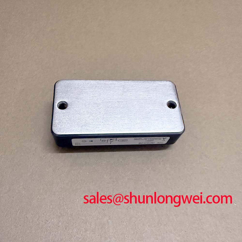
Before mounting the CM75E3Y-24E, clean the heatsink contact area and inspect it under direct light for burrs, embedded debris, gouges, corrosion, or old hardened thermal compound. Check the module baseplate externally for damage that could prevent full contact. A clean interface is necessary because trapped particles can create a localized gap and interfere with heat transfer.
Thermal interface material should be spread as a uniform, thin layer rather than deposited in isolated heavy spots. The required thickness is a General Industry Design Consideration, not an official Mitsubishi Electric requirement for this part. The correct material, layer control, mounting sequence, and fastener torque are determined by the module documentation, heatsink flatness, fastener specification, and equipment assembly procedure.
Tighten mounting hardware progressively in the specified sequence so the baseplate seats evenly against the heatsink. Applying full force to one corner first can leave uneven contact elsewhere. After mounting, inspect for excess grease pushed into nearby terminal areas and confirm that busbars align naturally without forcing the module body or twisting the power terminals. Mechanical stress should never be used to correct a busbar alignment problem.
For post repair commissioning, record the inverter fault state before clearing it, verify cooling fan or liquid loop operation as applicable, and monitor the equipment under the approved staged test procedure. Temperature imbalance, unusual acoustic noise, or repeated protection events may indicate a condition in the wider system and should be investigated with measured evidence. No field lifetime, failure rate, cosmic ray robustness, or single event burnout claim can be made for this module without a relevant authoritative source and defined operating conditions.
Where forklift or warehouse traction equipment is being returned to service, verify the enclosure sealing, connector retention, cable strain relief, and cooling path after the electrical work is complete. These checks help ensure that the installed CM75E3Y-24E remains assessed as part of the complete inverter assembly rather than as an isolated component.